Calibration system and calibration method for heliostat of solar generating station

A calibration system and heliostat technology, applied in the field of solar power generation, can solve the problems of complex calibration process, mechanical error of heliostat, and reduced calibration accuracy, and achieve the effects of small mechanical error, fast calibration action, and improved calibration accuracy

Inactive Publication Date: 2012-02-15
深圳市联讯创新工场科技开发有限公司
View PDF6 Cites 26 Cited by
  • Summary
  • Abstract
  • Description
  • Claims
  • Application Information

AI Technical Summary

Problems solved by technology

The control scheme is complicated, and the calibration process is complicated; at the same time, the multiple trajectory rotations of the heliostat introduce mechanical errors, and the calibration accuracy is reduced
In addition, in larger power plants, the rotation of a large number of heliostats consumes power from the calibration motors that control the rotation of the heliostats
As another example, in US Patent US20100139644, although the rotation track of the heliostat is simplified compared with CN101918769A during calibration, in order to obtain the contour position of the reflected spot of the heliostat, the control system still needs to control a large number of heliostats to rotate until the camera can capture In this way, the reflected light spot of the heliostat cannot be irradiated on the receiver, which affects the power generation efficiency

Method used


Image

  • Calibration system and calibration method for heliostat of solar generating station
  • Calibration system and calibration method for heliostat of solar generating station
  • Calibration system and calibration method for heliostat of solar generating station

Examples


Embodiment 1

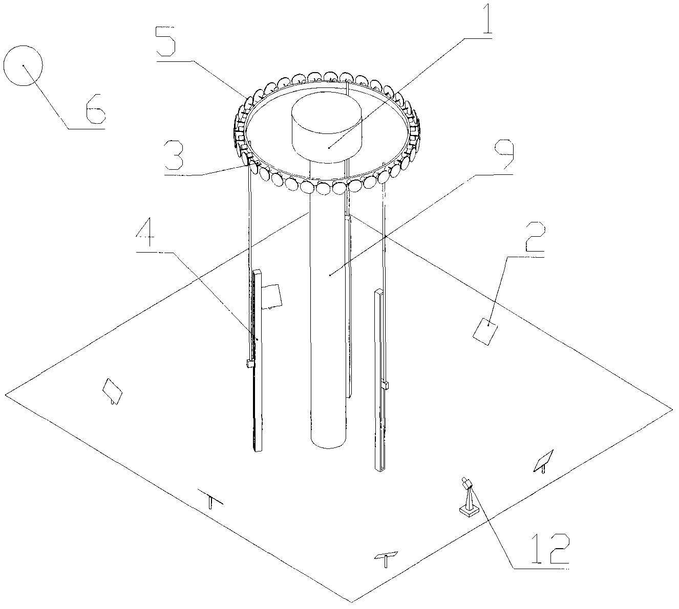
[0060] figure 2 Shown is a heliostat calibration system for a solar power plant, which includes a receiver 1 mounted on a support tower 9 that receives sunlight reflected by a heliostat 2 to directly generate steam or electricity; The height of the receiver 1 from the ground ensures that all the heliostats 2 in the heliostat field can be reflected onto the receiver 1 .

[0061] It also includes a heliostat field installed around the receiver; the heliostat field includes at least one heliostat 2; the heliostat 2 is configured with two rotation axes, and the heliostat 2 revolves The rotating shaft performs pitching rotation and panning rotation; the dual rotating shafts are equipped with angle sensors, which are used to accurately measure the actual pitching angle that the two rotating shafts rotate through and the pan angle ω. The heliostat 2 tracks the moving sun by adjusting the orientation of the mirror, so that the sunlight is continuously reflected to the receiver 1 ....

Embodiment 2

[0088] Figure 7 Shown is the heliostat calibration system of this embodiment, the difference between this calibration system and the calibration system in Embodiment 1 is:

[0089] The calibration light source in this embodiment is an artificial light source. The artificial light source is arranged on the receiver 1 . As another possible implementation mode, the artificial light source can also be set on the movable image sensor 3, such as Figure 8 shown. In this way, even if a large number of heliostats irradiate the reflected light spots on the image sensor group, the total energy will be much lower than that of sunlight as the calibration light source. There is no need for the above-mentioned dimming devices with widely varying degrees of dimming.

[0090] When the error of the heliostat is small, it is only necessary to calibrate the pitch angle and pan angle error of the heliostat. In this embodiment, the calibration error is: pitch angle and roll angle error of th...

Embodiment 3

[0100] Figure 9 It is the calibration system in this embodiment, which is basically the same as the calibration system in Embodiment 1, the difference is that:

[0101] The image sensor The image sensor 3 is mounted on a rotating mounting bracket 8, the rotating mounting bracket 8 can rotate around the support tower 9 of the receiver 1, the image sensor group is arranged vertically, and it is connected to the The rotating mounting bracket 8 rotates around the supporting tower 9 at the same time. The control unit obtains the central position of the light spot reflected by the heliostat through the rotation of the image sensor group.

[0102] The heliostat is equipped with two rotation axes X-axis and Y-axis parallel to the horizontal plane, and the heliostat performs pitch rotation around the two rotation axes respectively; the two rotation axes are respectively equipped with angle sensors for It is used to accurately determine the pitch angle through which the two rotation ...


PUM


Abstract

The invention discloses a calibration system for a heliostat of a solar generating station, which comprises a receiver, a heliostat field, an image sensor group and a control unit, wherein the heliostat field is arranged at the periphery of the receiver; the image sensor group is used for capturing a reflecting light spot radiated by a calibration light source onto the heliostat; the image sensor group can be movably arranged between the receiver and the heliostat field; at least one part of a reflecting image of the heliostat to be calibrated falls within the acquisition range of the image sensor group; and the control unit is used for acquiring the central position of the light spot reflected by the heliostat according to image information of the image sensor group and finally obtaining an error value of the heliostat to be calibrated. According to the calibration system disclosed by the invention, the central position of the reflecting light spot of the heliostat is determined by the movement of the image sensor group; and the calibration system has the advantages of high calibration speed, small mechanical error and improved calibration precision. The invention also discloses a calibration method of the calibration system.

Description

technical field [0001] The invention belongs to the field of solar power generation, and in particular relates to a heliostat calibration system and a tracking method of a solar power station. Background technique [0002] In a central tower receiver power plant, the receiver on top of the tower receives sunlight reflected from the heliostat array. The receiver converts the incident radiant energy to output high-pressure, high-temperature steam, which can then be sent to a turbine for electricity generation. Heliostats are generally installed on the ground around the tower. Each heliostat has a rigid reflective surface to track the sun, and the surface is oriented to the sun during the day to keep reflecting moving sunlight to the receiver. Highly accurate tracking of the sun is required to reduce reflected light spilling around the receiver. Therefore, providing a heliostat calibration system capable of accurately tracking the sun and achieving less loss has become an ur...

Claims


Application Information

Patent Timeline
Patent Type & Authority Applications(China)
IPC IPC(8): G05D3/12G01B11/00
CPCG01B11/26F24S2050/25G01B11/272
Inventor 孙海翔朱亮许迪窦新国王威钟强
Owner 深圳市联讯创新工场科技开发有限公司
Why Eureka
Try Eureka