Heliostat calibration method and system for solar power station
A calibration method and calibration system technology, which is applied in the field of solar power generation, can solve the problems of low calibration efficiency and low calibration accuracy, and achieve the effects of high calibration efficiency, high calibration accuracy, and small mechanical errors
- Summary
- Abstract
- Description
- Claims
- Application Information
AI Technical Summary
Problems solved by technology
Method used
Image
Examples
Embodiment 1
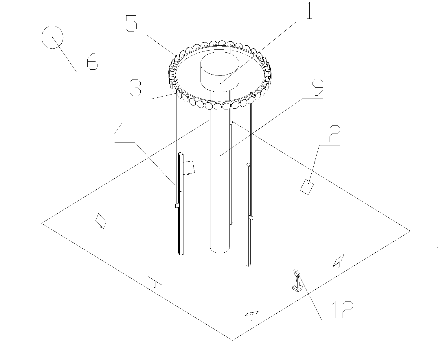
[0062] figure 2 Shown is a heliostat calibration system for a solar power plant, which includes a receiver 1 mounted on a support tower 9 that receives sunlight reflected by a heliostat 2 to directly generate steam or electricity; The height of the receiver 1 from the ground ensures that all the heliostats 2 in the heliostat field can be reflected onto the receiver 1 .
[0063] It also includes a heliostat field installed around the receiver; the heliostat field includes at least one heliostat 2; the heliostat 2 is configured with two rotation axes, and the heliostat 2 revolves The rotating shaft performs pitching rotation and panning rotation; the dual rotating shafts are equipped with angle sensors, which are used to accurately measure the actual pitching angle that the two rotating shafts rotate through and the pan angle ω. The heliostat 2 tracks the moving sun by adjusting the orientation of the mirror, so that the sunlight is continuously reflected to the receiver 1 ....
Embodiment 2
[0095] Figure 8 Shown is the heliostat calibration system of this embodiment, the difference between this calibration system and the calibration system in Embodiment 1 is:
[0096] The calibration light source in this embodiment is artificial light source 7 . The artificial light source 7 is arranged on the receiver 1 . As another possible implementation mode, the artificial light source can also be set on the movable image sensor 3, such as Figure 9 shown. In this way, even if a large number of heliostats irradiate the reflected light spots on the image sensor group, the total energy will be much lower than that of sunlight as the calibration light source. There is no need for the above-mentioned dimming devices with widely varying degrees of dimming.
Embodiment 3
[0098] Figure 10 It is the calibration system in this embodiment, which is basically the same as the calibration system in Embodiment 1, the difference is that:
[0099] The image sensor The image sensor 3 is mounted on a rotating mounting bracket 8, the rotating mounting bracket 8 can rotate around the support tower 9 of the receiver 1, the image sensor group is arranged vertically, and it is connected to the The rotating mounting bracket 8 rotates around the supporting tower 9 at the same time. The control unit obtains the central position of the light spot reflected by the heliostat through the rotation of the image sensor group.
[0100] The heliostat is equipped with two rotation axes X-axis and Y-axis parallel to the horizontal plane, and the heliostat performs pitch rotation around the two rotation axes respectively; the two rotation axes are respectively equipped with angle sensors for It is used to accurately determine the pitch angle through which the two rotation...
PUM
 Abstract
Description
Claims
Application Information
 - R&D
- Intellectual Property
- Life Sciences
- Materials
- Tech Scout
- Unparalleled Data Quality
- Higher Quality Content
- 60% Fewer Hallucinations
Browse by: Latest US Patents, China's latest patents, Technical Efficacy Thesaurus, Application Domain, Technology Topic, Popular Technical Reports.
© 2025 PatSnap. All rights reserved.Legal|Privacy policy|Modern Slavery Act Transparency Statement|Sitemap|About US| Contact US: help@patsnap.com


