
Wake-up reset circuit

A reset circuit and circuit technology, applied in data reset devices, electronic switches, electrical components, etc., can solve the problems of shortened battery life, unpredictable "sub-stable" state of digital logic circuits, etc.

Active Publication Date: 2012-02-15
MICROCHIP TECH INC
View PDF3 Cites 6 Cited by
  • Summary
  • Abstract
  • Description
  • Claims
  • Application Information

AI Technical Summary

Problems solved by technology

For electronic components that rely on batteries, especially for components that are expected to operate for a long time, this quiescent current is an important factor in reducing the life of the battery
Other issues inherent to POR and / or brownout circuits are proper operation when power supplies are below critical voltages, making digital logic circuits in unpredictable "sub-stable" states and when applied in electrically noisy environments

Method used


Image

  • Wake-up reset circuit
  • Wake-up reset circuit
  • Wake-up reset circuit

Examples


Embodiment Construction

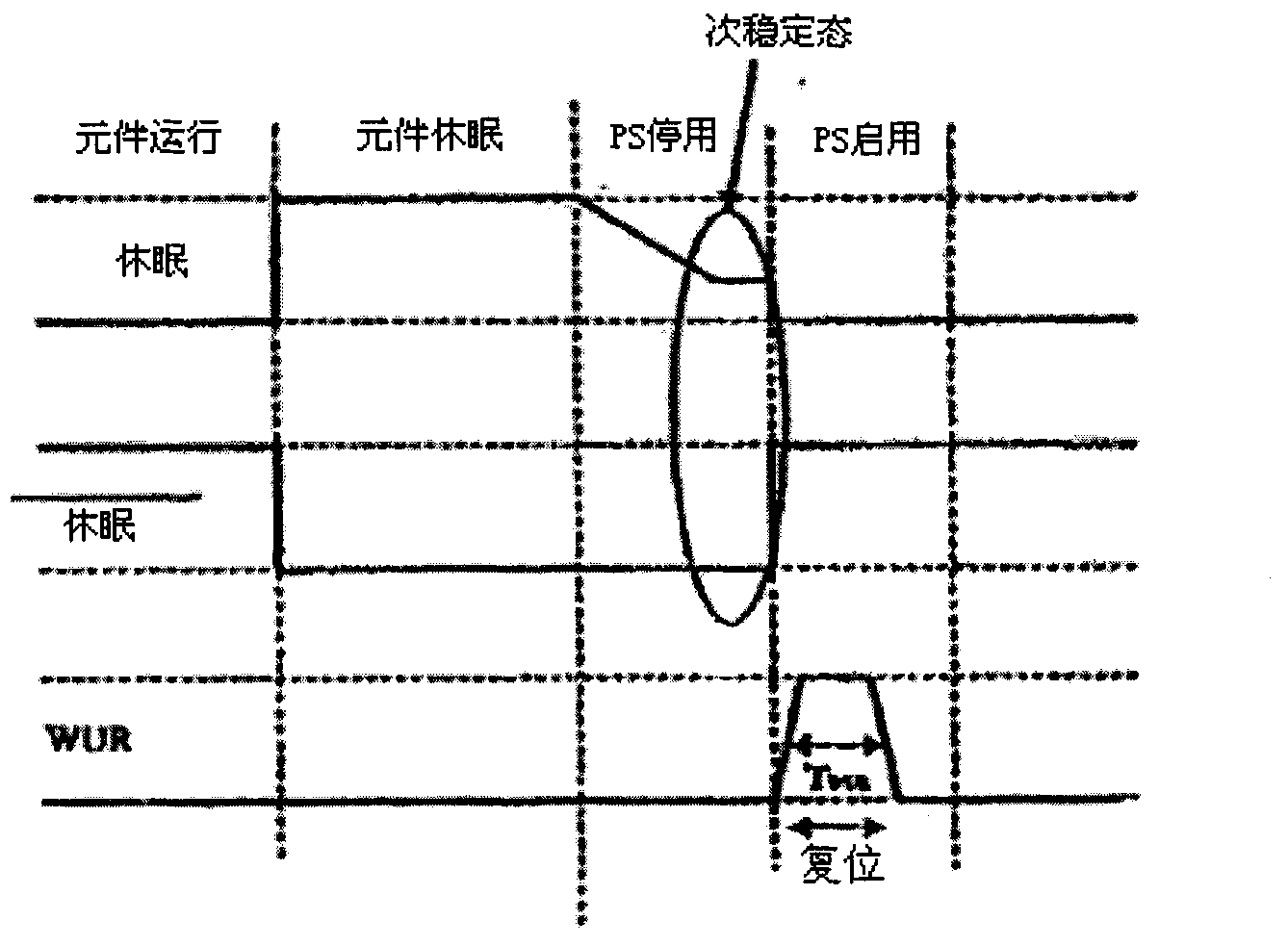
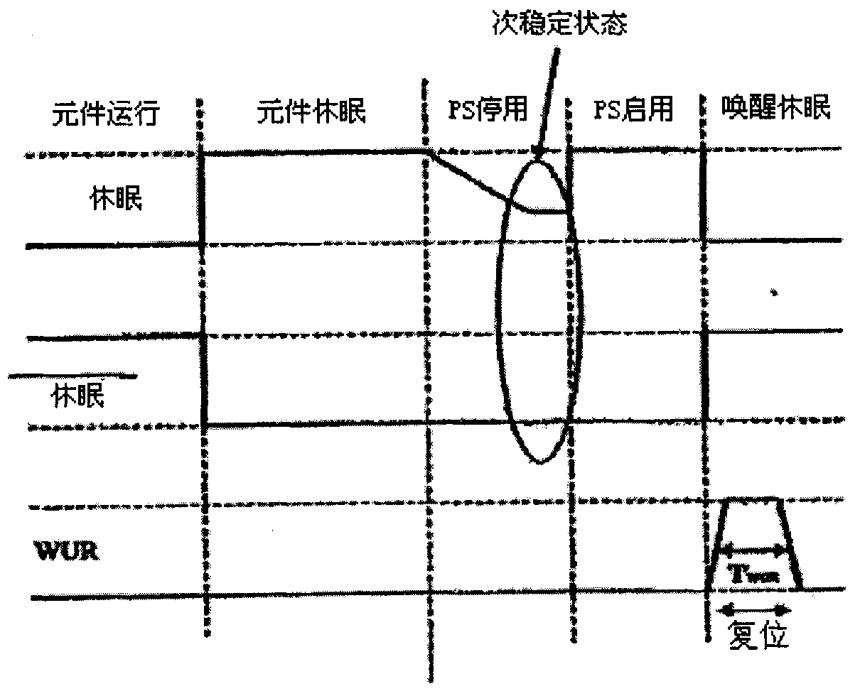
[0019] Any time a digital component (such as a digital processor, microcontroller, microprocessor, application specific integrated circuit (ASIC), programmable logic array (PLA), digital signal processor (DSP) ), etc.) upon receiving the wake-up signal, the present invention executes the wake-up reset of the digital element.

[0020] Referring now to the drawings, details of specific embodiments of the invention are schematically illustrated. Like elements in the drawings will be denoted by the same numerals, and similar elements will be denoted by the same numerals with a different lowercase letter suffix.

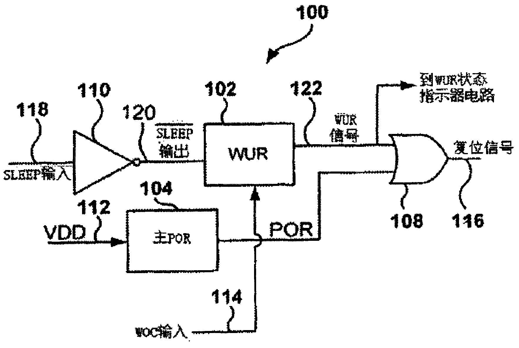
[0021] see now figure 1 , which depicts a schematic logical block diagram of certain exemplary embodiments of the present invention. Wake-up reset (“WUR”) module (generally indicated at 100 ) includes wake-up reset (“WUR”) circuit 102 , master power-on reset (POR) 104 and OR gate 108 . Inverter 110 is optionally used to invert SLEEP input 118 into a / SLEEP output 120, ...


PUM


Abstract

A wake-up reset circuit is provided that generates a reset signal to a digital circuit upon a wake-up event. The wake-up reset circuit places the digital circuit into a known reset condition upon wake-up, even if a brown out condition occurs which may have caused unstable and unknown logic states in sequential circuit elements, e.g., volatile memory, flip flops and / or latching circuits. The wake-up reset circuit draws substantially no current when not generating the reset signal.

Description

[0001] This application is a divisional application of an invention patent application with an application date of December 15, 2004, an application number of 200480038165.2, and an invention title of "wake-up and reset circuit". technical field [0002] The present invention basically relates to digital electronic circuits. More particularly, the present invention relates to wake-up reset circuits that generate an integrated circuit ("chip") reset after a wake-up event occurs. Background technique [0003] Electronic circuits have been used to monitor power supply voltages of electronic components in order to detect voltage thresholds required to generate a power-on reset ("POR") for the electronic components. The same or other circuits have been used to detect brownout or brownout conditions. Typically POR and brownout detection circuits always require quiescent current to function. For electronic components that rely on batteries, especially for components that are expe...

Claims


Application Information

Patent Timeline
Patent Type & Authority Applications(China)
IPC IPC(8): G06F1/24H03K17/22
CPCG06F1/24H03K17/22
Inventor 哈托诺·达尔马瓦斯克伊塔莱顿·W·伊格斯科特·瑞安·埃利森维维安·德尔波特
Owner MICROCHIP TECH INC
Learn More