
Method for analyzing out-of-plane motion of steel catenary riser

An analysis method and motion analysis technology, applied in special data processing applications, instruments, electrical digital data processing, etc., can solve the problem that the calculated value is too small, does not consider the influence of inertial force and additional mass of steel catenary riser, ignores problems with acceleration

Inactive Publication Date: 2012-02-15
OCEAN UNIV OF CHINA
View PDF1 Cites 7 Cited by
  • Summary
  • Abstract
  • Description
  • Claims
  • Application Information

AI Technical Summary

Problems solved by technology

[0016] 1. The influence of the acceleration caused by the rotation of the rigid body on the inertial force and additional mass of the steel catenary riser is not considered
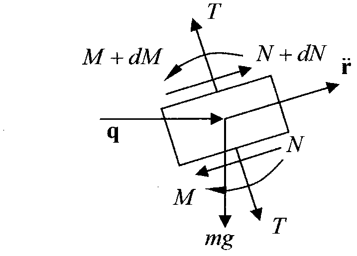
[0017] The inertial force item in the dynamic balance equation of the structure (the first item in the bending motion equation of the beam) should be the absolute acceleration of the structure, but the prior art uses the acceleration caused by bending deformation, ignoring the acceleration caused by the rotation of the rigid body , therefore, the calculated value is small
[0018] 2. The influence of the speed caused by the rotation of the rigid body on the additional damping and hydrodynamic load of the steel catenary riser is not considered
[0019] The damping force item in the dynamic balance equation of the structure (the second item in the bending motion equation of the beam) is divided into two parts, one part is the damping of the structure itself (the first part of the second term in the beam's bending equation of motion), and the other part is the additional damping of the hydrodynamic force (the second part of the second term in the bending motion equation of the beam), the size of this part of the damping depends on the relative velocity of the structure and the fluid, therefore, it should be the absolute velocity of the structure, but what the prior art uses is that the bending deformation causes The velocity caused by the rotation of the rigid body is ignored, so the calculated value is too small

Method used


Image

  • Method for analyzing out-of-plane motion of steel catenary riser
  • Method for analyzing out-of-plane motion of steel catenary riser
  • Method for analyzing out-of-plane motion of steel catenary riser

Examples


Embodiment Construction

[0086] The present invention will be described in detail below in conjunction with the accompanying drawings and specific embodiments.

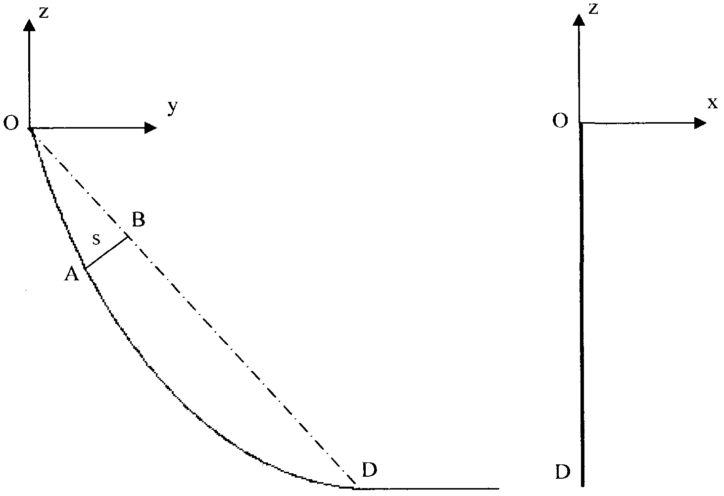
[0087] A steel catenary riser is a free-hanging steel tube with an axis in the shape of a catenary. Its top is suspended on the floating platform, and its lower end extends directly to the seabed. The first point of contact with the seabed is the touchdown point. The section from the suspension point to the touchdown point is called the overhang section, and the section on the seabed is called the streamline section. Thus, the touchdown point is the point of separation of the overhang and streamline segments. Since the suspension section is a catenary line, when the steel catenary riser moves in a plane (the plane composed of catenary lines), the movement of the suspension section will also form around the suspension point and the contact point when the bending deformation occurs. The axis of rotation is a rigid body rotational motion. Tha...


PUM


Abstract

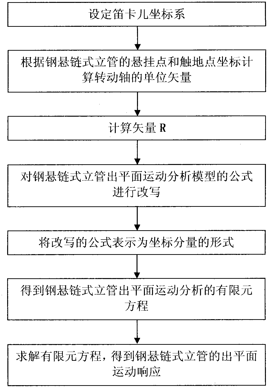
The invention relates to a research method for marine deepwater risers, and particularly relates to a method for analyzing the out-of-plane motion of a steel catenary riser. By using the method disclosed by the invention, an improvement on the existing technique for analyzing the out-of-plane motion of a steel catenary riser is performed, the rigid body motion of the out-of-plane motion of a steel catenary riser is taken into consideration, an analytical mode of the out-of-plane motion of a steel catenary riser is built, and the rigid body rotation of the out-of-plane motion of a steel catenary riser is added, so that the analysis on the out-of-plane motion of a steel catenary riser is more consonant with an actual motion state.

Description

technical field [0001] The invention relates to a research method of an ocean deepwater riser, in particular to a method for analyzing the out-of-plane motion of a steel catenary riser. Background technique [0002] Steel catenary risers, umbilical cables and flexible risers are important equipment for deep-sea oil and gas development. One end of them is connected to the floating platform and hangs freely to the seabed, forming a catenary. The first point where the steel catenary riser, umbilical and flexible riser contacts the seabed is called the touchdown point, and the section from the floating platform to the touchdown point is called the suspension section. The other end of the steel catenary riser, umbilical and flexible riser is connected to the wellhead (production riser) or subsea terminal (transport riser) or subsea manifold, from the touchdown point to the wellhead, subsea terminal or subsea manifold A segment of is called a streamline segment. [0003] Steel c...

Claims


Application Information

Patent Timeline
Patent Type & Authority Applications(China)
IPC IPC(8): G06F19/00
Inventor 黄维平杨超凡李倩
Owner OCEAN UNIV OF CHINA
Learn More