Novel broad-band microstrip surface-mounted antenna array

A microstrip patch antenna and wide-band technology, applied in the direction of antenna array, antenna, radiation element structure, etc., can solve the problems of spending a lot of time and energy, unable to further adjust, and thin feeder lines, etc., to achieve simple structure, Effects of Simplifying the Design Debug Process

Inactive Publication Date: 2012-02-15
LINGBAYI ELECTRONICS GRP
View PDF3 Cites 9 Cited by
  • Summary
  • Abstract
  • Description
  • Claims
  • Application Information

AI Technical Summary

Problems solved by technology

An array composed of the same antenna elements can bring convenience in simulation modeling and design, especially for very large arrays composed of hundreds or thousands of antenna elements. However, for small aperture-coupled microstrip patch antenna arrays limits the degree of freedom of parameter adjustment
For example, in order to obtain a lower antenna sidelobe level, it is necessary to adjust the feed amplitude distribution of each unit. In the case of equal-length coupling slots, only the impedance of the feed line of each unit can be adjusted (reflected on the printed graph of the feed line That is, to adjust its width), and at the same time adjust the corresponding impedance transformation section of the feeder line. Sometimes the feeder line is very thin and cannot be further adjusted, and the processing of the thinner microstrip line will also bring greater processing Error, this debugging process is very cumbersome, it takes a lot of time and energy, the result may not meet the requirements

Method used


Image

  • Novel broad-band microstrip surface-mounted antenna array
  • Novel broad-band microstrip surface-mounted antenna array
  • Novel broad-band microstrip surface-mounted antenna array

Examples


Embodiment Construction

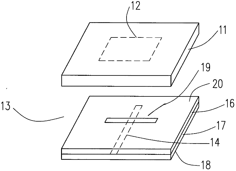
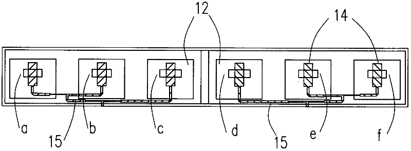
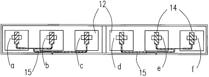
[0011] Such as figure 1 , figure 2 As shown, an embodiment of the present invention includes an array body 1, the array body 1 is composed of several radiating units provided with coupling slots, and the length of the coupling slots of each radiating unit is set on the array body 1 from the middle to the two sides. The array body 1 is provided with six radiating units, and the radiating units provided with coupling slots of the same length are arranged in pairs on the array body 1. The six radiating units include six coupling slots; the six coupling slots include The first coupling slot a, the second coupling slot b, the third coupling slot c, the fourth coupling slot d, the fifth coupling slot e, and the sixth coupling slot f are arranged in order from left to right; the first coupling slot a and the sixth coupling slot The length of the six coupling slots f is equal to 48 mm; the length of the second coupling slot b and the fifth coupling slot e are equal to 50 mm; the len...


PUM


Abstract

A novel broad-band microstrip surface-mounted antenna array comprises an array body, which comprises a plurality of radiating elements with coupling grooves, and the novel broad-band microstrip surface-mounted antenna array is characterized in that in terms of an arrangement mode, the length of the coupling groove of each radiating element is gradually reduced from the middle to both ends on the array body. In one improvement, the array body is provided with six radiating elements, and the radiating elements with equilong coupling grooves are arranged in pairs on the array body. The structure of the novel broad-band microstrip surface-mounted antenna array is simple, the design and debugging process of the novel broad-band microstrip surface-mounted antenna array is simple and convenient, feeders do not need to be adjusted at the stage of simulation design, and the beam width, side lobes, gain and other radiation properties of the antenna array can be visually and conveniently observed on a computer.

Description

technical field [0001] The invention relates to a microstrip patch antenna array structure, in particular to a small aperture-coupled microstrip patch antenna array. Background technique [0002] Microstrip antenna is a new type of antenna successfully developed in the early 1970s. Compared with common microwave antennas, it has small size, light weight, low profile, conformal with the carrier, simple manufacture, low cost, and easy integration with microstrip antennas. Line integration and other features. Microstrip patch antenna is a kind of microstrip antenna, which is widely used because of its relatively high efficiency and mature analysis methods, but its narrow frequency band limits its application field. [0003] The narrow-band characteristic of the microstrip patch antenna is determined by its high-Q resonant nature. This means that a match is achieved when at resonance, but a mismatch is caused by a sharp shift in the reactive component as the frequency moves aw...

Claims


Application Information

Patent Timeline
Patent Type & Authority Applications(China)
IPC IPC(8): H01Q1/36H01Q21/00
Inventor 陈斌王学良李福军赵玉国卿海钱俊辉曾传宝汪波
Owner LINGBAYI ELECTRONICS GRP
Why Eureka
Try Eureka