Protection method of cascaded converter

A converter and cascading technology, applied to emergency protection circuit devices, irreversible DC power input conversion to AC power output, AC power input conversion to DC power output, etc., can solve the problem of affecting the normal operation of the converter unit , unfavorable application of cascaded inverters, insufficient adjustment speed and other problems, to achieve the effect of reliable active voltage equalization method, prolonging the trouble-free running time and good protection effect

Active Publication Date: 2015-04-29
CHINA EPRI SCIENCE & TECHNOLOGY CO LTD +2
View PDF2 Cites 2 Cited by
  • Summary
  • Abstract
  • Description
  • Claims
  • Application Information

AI Technical Summary

Problems solved by technology

For cascaded converters, the voltage equalization method is mainly aimed at the normal operation of the converter, that is, the voltage equalization control strategy in the unlocked state; for the blocked standby state, a single converter unit is in an uncontrollable rectification state, and there is still a lack of Effective Pressure Equalization Method
[0005] Moreover, when the start-up time is long or the standby state is long, the DC bus voltage imbalance of each converter unit will gradually increase over time, which may exceed the normal operating range of the components and cause damage to the components, or affect the converter. normal operation of the unit
[0006] There are various overvoltage protection strategies currently available, and their specific implementation uses the inverter bridge of the converter unit. In order to maintain the stability of the entire system, when the voltage deviation of the converter unit is large, there may be too long response time or If the adjustment speed is not fast enough and other problems, when a single converter unit has an overvoltage fault, the entire system can only be withdrawn
For the overvoltage protection of a single converter unit, when a single converter unit cannot continue to work due to overvoltage problems, only the entire system is blocked and exited, and the system is too frequently exited, for the application of cascaded inverters very unfavorable

Method used


Image

  • Protection method of cascaded converter
  • Protection method of cascaded converter
  • Protection method of cascaded converter

Examples


Embodiment Construction

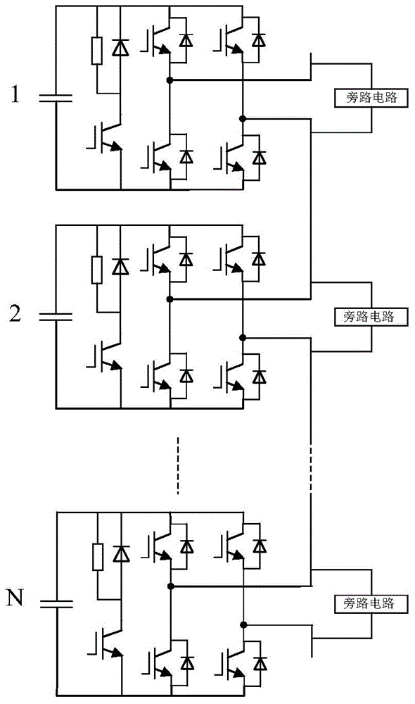
[0039] The specific implementation manners of the present invention will be further described in detail below in conjunction with the accompanying drawings.

[0040] Such as figure 1 As shown in the cascaded converter, the converter is composed of a full-bridge circuit and capacitors connected in parallel, and the AC sides of N converters are connected in series to form a cascaded converter; this embodiment is above this: (1) in A discharge circuit is arranged in parallel at both ends of the capacitor; (2) A bypass circuit is connected in parallel at the AC side of each converter. The structure of the discharge circuit is: the anode of the diode is connected to the collector of the IGBT, the cathode of the diode is connected to the positive pole of the DC bus; the negative pole of the DC bus is connected to the emitter of the IGBT to realize the parallel connection of the discharge circuit and the DC bus. The full-bridge circuit is an H-bridge structure, including two complete ...


PUM


Abstract

The invention provides a cascaded converter and a protection method thereof. A discharge loop and a bypass circuit are added into the converter, and simultaneously, an active voltage equalizing method or an overvoltage protection method is used for monitoring the converter to ensure that the direct-current bus voltage of each transformer in the cascaded converter is in a balanced state, or the overvoltage protection is performed when the voltage is overhigh. In the invention, the active voltage equalizing method obtains a good effect through tests. In the invention, the overvoltage protection method and the active voltage equalizing control method adopt the same circuit, a fast protection method is provided, a good protection effect can be obtained, the failure-free operation time of a system is prolonged, and a foundation is provided for the application of the cascaded converter. The invention has important significance for the application of cascaded converters in the future.

Description

Technical field: [0001] The invention relates to the field of power electronics, in particular to a cascaded converter and a protection method thereof. Background technique: [0002] The cascaded converter consists of N independent full-bridge circuits or half-bridge circuits connected in series on the AC side, and the DC sides are independent of each other. A three-phase system can be formed by 3 bridge arm pairs through Y-type or △-type connection. Used in various high-voltage power electronic devices. This kind of cascaded converter has many advantages: the structure of each converter unit is the same, and it is easy to realize modular design, installation and maintenance; The converter unit works symmetrically and the switch load is balanced; after cascading, low-voltage components can be used to achieve high-voltage output, combined with other technologies such as carrier shift, lower harmonic distortion can be obtained, and a lower switching frequency can be used, th...

Claims


Application Information

Patent Timeline
Patent Type & Authority Patents(China)
IPC IPC(8): H02M7/49H02M1/32H02H7/122
CPCH02M1/32H02M1/325H02M7/4835
Inventor 王轩武丹韩天绪张佃青袁蒙孙丽敬李志伟郑斌毅林嘉扬
Owner CHINA EPRI SCIENCE & TECHNOLOGY CO LTD
Why Eureka
Try Eureka