Electric flanging machine for steel pipes

A flanging machine and electric technology, which is applied in the field of flanging machines, can solve the problems of high labor intensity, low work efficiency, and unguaranteed quality, and achieve the effect of ensuring product quality

Inactive Publication Date: 2012-02-22
汪涛
View PDF7 Cites 6 Cited by
  • Summary
  • Abstract
  • Description
  • Claims
  • Application Information

AI Technical Summary

Problems solved by technology

[0002] The connection between the tap water steel pipes is usually realized by threads. In order to prevent the compression screw sleeve on the steel pipe from falling off, it is necessary to set the anti-thrust turning edge at the

Method used


Image

  • Electric flanging machine for steel pipes
  • Electric flanging machine for steel pipes

Examples


Example Embodiment

[0011] The present invention and its specific implementations will be described in further detail below in conjunction with the accompanying drawings.

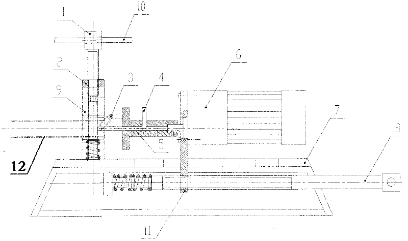
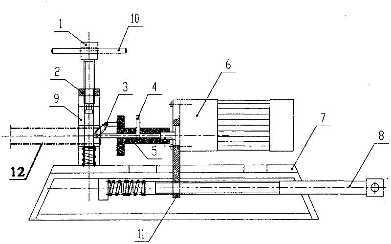
[0012] Referring to the accompanying drawings, the present invention includes a screw mandrel, an adjusting rod with rollers and a base, and is characterized in that:

[0013] A, one end of the screw mandrel 1 passes through the screw mandrel frame 2 and is connected to the clamping block 9; the other end is connected to the screw mandrel wrench 10;

[0014] B, one end of the adjusting rod 3 with rollers is connected with the motor 6, and the other end is positioned at the side of the screw mandrel 1;

[0015] C. The base 7 is provided with a motor screw 8, which is threadedly connected with the sliding seat 11, and the edge of the sliding seat is installed in the chute of the base 7 and can move along the chute.

[0016] First insert one end of the steel pipe to be flanged into the clamping block 9 of the screw rack 2, tight...


PUM


Abstract

The invention discloses an electric flanging machine for steel pipes. The invention aims to provide the electric flanging machine for the steel pipes for replacing manual flanging operation. The electric flanging machine comprises a lead screw, an adjusting rod with a roller and a base. The electric flanging machine is characterized in that: A, one end of the lead screw passes through a lead screw rack and is connected with a clamping block, and the other end of the lead screw is connected with a lead screw spanner; B, one end of the adjusting rod with the roller is connected with a motor, and the other end of the adjusting rod is positioned on the lateral surface of the lead screw; and C, a motor lead screw is arranged in the base, the motor lead screw is in threaded connection with a sliding seat, and the edge of the sliding seat is arranged in a chute of the base and can move along the chute. The electric flanging machine is mainly applied to steel pipe flanging.

Description

technical field [0001] The invention relates to a flanging machine, in particular to an electric steel pipe flanging machine. Background technique [0002] The connection between the tap water steel pipes is usually realized by threads. In order to prevent the compression screw sleeve on the steel pipe from falling off, it is necessary to set the anti-thrust turning edge at the end of the steel pipe. The anti-thrust turning edge in the prior art is manually Prepared by beating or manual extrusion, it is time-consuming, labor-intensive, low-efficiency, labor-intensive, and the quality cannot be guaranteed. Contents of the invention [0003] The purpose of the present invention is to provide an electric steel pipe flanging machine to replace manual work and overcome the above drawbacks. [0004] In order to achieve the above object, the technical solution of the present invention is: 1. An electric steel pipe flanging machine, comprising a screw mandrel, an adjusting rod wi...

Claims


Application Information

Patent Timeline
IPC IPC(8): B21D19/12
Inventor 汪涛汪波彭春来
Owner 汪涛
Why Eureka
Try Eureka