Injection mold screw thread core pulling mechanism

A core-pulling mechanism and injection mold technology, which is applied to threaded products, other household appliances, household appliances, etc., can solve the problems of large power and volume of servo motors, increase the volume occupied by molds, and difficulty in ensuring accuracy, and achieve push-out resistance Stable and uniform, easy to ensure manufacturing accuracy, and simplified mechanism

Inactive Publication Date: 2012-02-22
SHUNDE POLYTECHNIC
View PDF6 Cites 7 Cited by
  • Summary
  • Abstract
  • Description
  • Claims
  • Application Information

AI Technical Summary

Problems solved by technology

[0004] This mechanism can synchronize the rotation and extraction of the push plate and the threaded core, breaking through the limitations of the traditional mechanical thread removal structure. However, this system has three main disadvantages. One is that the ejection mechanism is complicated.
The action of the push plate needs to be transmitted through the ejector plate, the action of the ejector plate is driven by the rack, and the action of the rack is driven by the worm gear. In this way, the manufacturing accuracy is difficult to guarantee; especially the ejector plate and the rack. Connection, because the rack is not pushed eccentrically in the center of the thimble plate, it will cause an increase in thrust, because even if the thimble plate is slightly inclined, it will generate greater friction at the guide post of the thimble plate; the second is the worm gear Although the deceleration mechanism is beneficial to reduce the driving force requirements of the servo motor, if the deceleration is 1:20, the driving force is 1 / 20 of the thrust of the rack, but the power and volume of the servo motor selected in this way are still relatively large; the third is The worm gear mechanism is placed outside the support plate of the mold, which increases the volume occupied by the mold and brings inconvenience to hoisting, etc.

Method used


Image

  • Injection mold screw thread core pulling mechanism
  • Injection mold screw thread core pulling mechanism
  • Injection mold screw thread core pulling mechanism

Examples


Embodiment Construction

[0026] The present invention will be further described below in conjunction with the accompanying drawings and examples. It should be understood that the specific embodiments described here are only used to explain the present invention, and are not intended to limit the present invention.

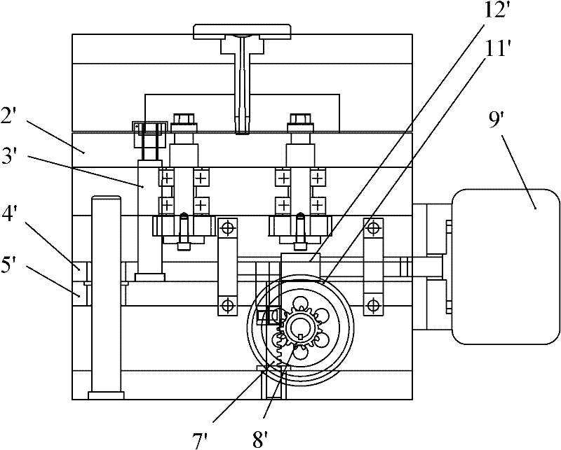
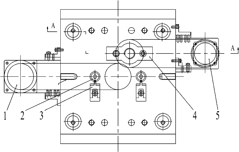
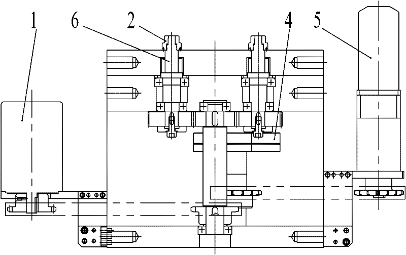
[0027] see figure 2 one Figure 4 , the threaded core-pulling mechanism of the injection mold includes a fixed template, a movable template, an injection molded part 2 and a threaded core 6 in the mold cavity, and a core-pulled mechanism for the threaded core 6, which is located at the bottom of the plastic injection molded part 2 and The push plate 11 and the push plate synchronous ejection mechanism for synchronous ejection during thread core pulling, the thread core 6 is connected with the core pulling mechanism, the push plate 11 is connected with the synchronous ejection mechanism, and the control system controls the motor speed of the two mechanisms so that the thread The stroke of...


PUM


Abstract

The present invention provides an injection mold screw thread core pulling mechanism. The mechanism comprises a mold cavity, an injection part, a screw thread type core inside the injection part, and a pushing plate arranged below the injection part. The screw thread type core is connected with a rotating core pulling mechanism. The pushing plate is connected with an ejection mechanism, and further comprises a PLC synchronization control system, wherein the screw thread type core pulling and the pushing plate have synchronous ejection travel through the PLC synchronization control system. The ejection mechanism comprises a servo motor, a sprocket pair and a screw rod nut pair, wherein the servo motor is connected with the sprocket pair, the sprocket pair is connected with the screw rod nut pair, the screw rod nut pair is connected with the pushing plate. The injection mold screw thread core pulling mechanism provided by the present invention has a reasonable and compact structure, and adopts the screw rod nut, such that the rotation movement is directly transformed into the linear movement, the ejection mechanism further becomes the labor-saving mechanism so as to reduce the torsional moment of the servo motor, conveniently install the mechanism. In addition, the injection mold screw thread core pulling mechanism provided by the present invention has significantly technical advancement.

Description

technical field [0001] The invention relates to an injection mold core-pulling mechanism, in particular to a servo-synchronous injection mold thread core-pulling mechanism. Background technique [0002] In the injection mold, if there are threads in the plastic part, the threaded core cannot be pulled out directly for forced removal, otherwise the internal thread structure of the plastic part will be easily damaged. The commonly used demoulding method is to configure an oil motor on the threaded core. , The oil motor drives the thread core to come out from the injection mold. The thread come out is realized by two actions. The rotation of the core is driven by the oil motor. The spring force changes with the stroke when pressing the plate, causing the action of pushing the plate to be inconsistent with the axial displacement of the screw thread. The reliability of this automatic thread removal mechanism is insufficient, especially when the thread length is long, the difficu...

Claims


Application Information

Patent Timeline
Patent Type & Authority Applications(China)
IPC IPC(8): B29C45/40B29L1/00
Inventor 畅国帏乡碧云
Owner SHUNDE POLYTECHNIC
Why Eureka
Try Eureka