Embedded dual-layer rolling harmonious reducer

A harmonic reducer, embedded technology, applied in the direction of mechanical equipment, transmission devices, gear transmission devices, etc., can solve the problems affecting the service life of the bearings in the reducer, unstable working conditions, unstable output, etc., to achieve stable work , stable output and high precision

Inactive Publication Date: 2012-02-22
SUZHOU LEADERDRIVE HARMONIC WAVE TRANSMISSION TECH CO LTD
View PDF7 Cites 0 Cited by
  • Summary
  • Abstract
  • Description
  • Claims
  • Application Information

AI Technical Summary

Problems solved by technology

[0003] However, the existing rolling harmonic reducer has a low degree of fit and unstable output, resulting in unstable overall wor

Method used


Image

  • Embedded dual-layer rolling harmonious reducer
  • Embedded dual-layer rolling harmonious reducer

Examples


Embodiment Construction

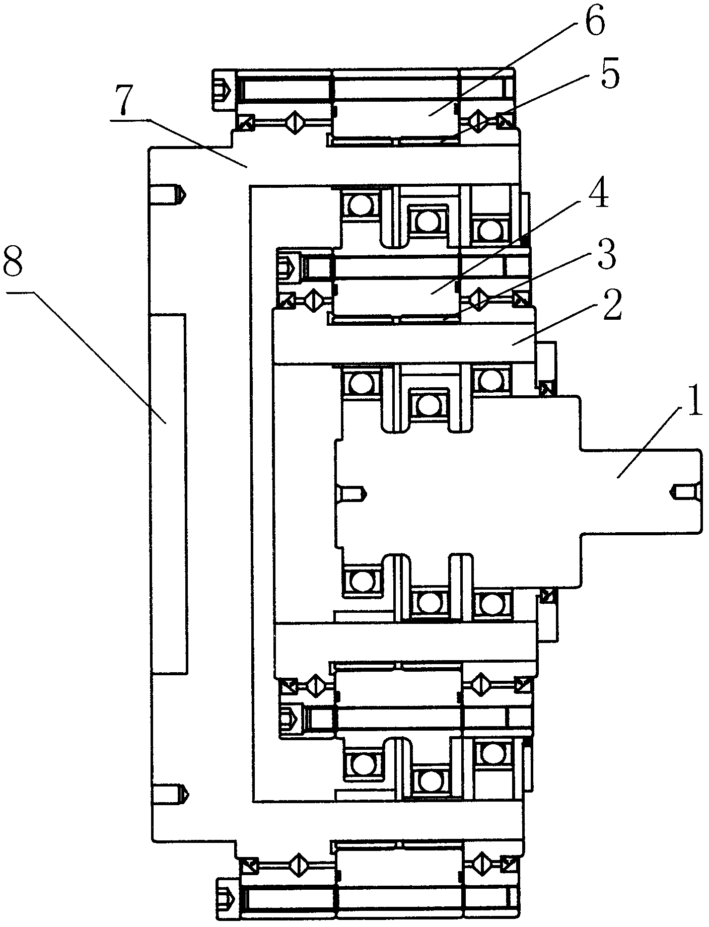
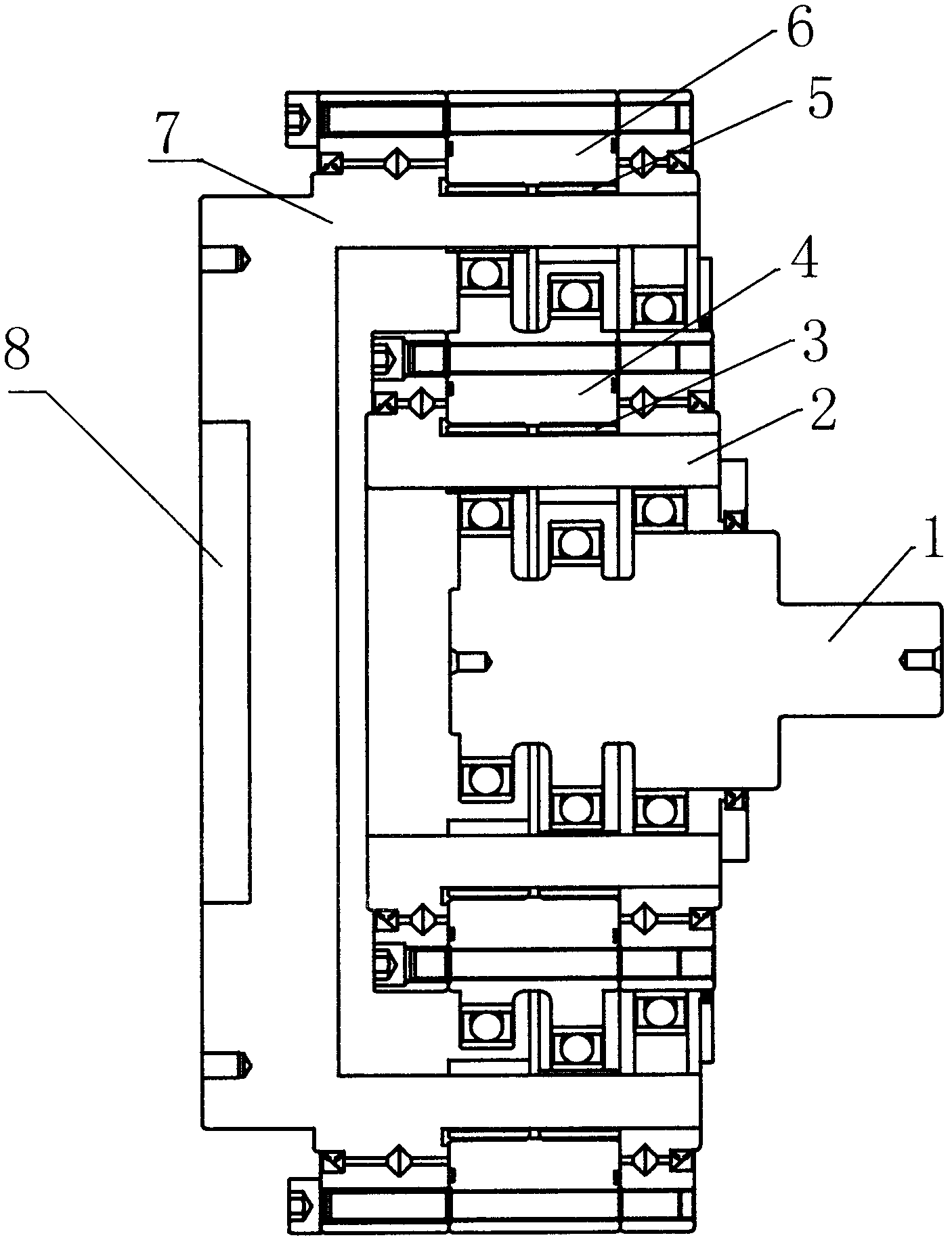
[0018] Such as figure 1 A mosaic double-layer rolling harmonic reducer shown includes an input end assembly 1, which is different in that a connecting shaft 2 is sheathed on the periphery of the input end assembly 1 used in the present invention. Moreover, in order to achieve the second-level deceleration, a nested double-layer layout is adopted. Specifically, in the present invention, an inner outer gear 4 is connected to the outer periphery of the connecting shaft 2 through an inner inner gear 3 assembly. At the same time, a bearing assembly is sheathed on the periphery of the inner outer gear 4 . In order to facilitate the connection of the entire reducer to be more compact and stable, the bearing assembly adopted in the present invention has a housing space distributed in the middle section, and an outer inner gear 5 assembly is sleeved around the housing space. Correspondingly, an outer outer gear 6 is sheathed on the periphery of the outer inner gear 5 assembly. As a ...


PUM


Abstract

The invention relates to an embedded dual-layer rolling harmonious reducer which comprises an input end assembly and is characterized in that a connecting shaft is sleeved on the periphery of the input end assembly, and inner layer external gears are connected to the periphery of the connecting shaft through an inner layer internal gear assembly. Meanwhile, a bearing assembly is sleeved on the peripheries of the inner layer external gears, an accommodating space is arranged at the middle section of the bearing assembly, an outer layer internal gear assembly is sleeved on the periphery of the accommodating space, and outer layer external gears are sleeved on the periphery of the outer layer internal gear assembly. Therefore, through meshing of two gears with a position difference of 180 DEG, the embedded dual-layer rolling harmonious reducer obtains the output of two times of torque compared with that of the single-layer rolling harmonious reducer, has more balance of couple and more stable output of the integral structure, and works more stably. Meanwhile, the inner layer external gears are used for dual cylinders to be meshed with the outer layer external gears, so that embedded dual-layer rolling harmonious reducer has more compact structure, higher precision, higher rigidity and difficulty in damage.

Description

technical field [0001] The invention relates to a speed reducer, in particular to a mosaic double-layer rolling harmonic speed reducer. Background technique [0002] Rolling harmonic reducer (Rolling Harmonious Reducer) referred to as RH reducer. After repeated trials and tests, the circular movement of the small cylinder in the inner wheel cavity can realize the differential meshing of the inner and outer gears, and make them move, so as to mesh with the outer wheel. Because every time the small cylinder turns a full circle, the corresponding point reaches an extreme value, that is, one tooth moves, so as to achieve the effect of deceleration. [0003] However, the existing rolling harmonic reducer has a low matching degree and unstable output, which leads to unstable working conditions as a whole. Furthermore, the rigidity of the overall parts is small, which affects the service life of the bearings in the reducer. Contents of the invention [0004] The object of the ...

Claims


Application Information

Patent Timeline
IPC IPC(8): F16H1/32
Inventor 左昱昱庄晓琴
Owner SUZHOU LEADERDRIVE HARMONIC WAVE TRANSMISSION TECH CO LTD
Why Eureka
Try Eureka