
Device for installing externally-clamping probes of portable ultrasonic flow meter

An installation device, ultrasonic technology, applied in the direction of measurement device, measurement of flow/mass flow, liquid/fluid solid measurement, etc., can solve the problems that the axis of the pipeline to be measured cannot be in the same plane, and the paper tape cannot be completely attached to the pipeline, etc. Achieve the effect of light weight, easy installation and good portability

Active Publication Date: 2012-02-22
SHANGHAI JIAO TONG UNIV +1
View PDF3 Cites 28 Cited by
  • Summary
  • Abstract
  • Description
  • Claims
  • Application Information

AI Technical Summary

Problems solved by technology

The principle of the coordinate method is simple, but there are the following deficiencies in the specific operation: 1) It cannot strictly ensure that the central axis planes of the two probes and the axis of the measured pipeline are in the same plane; 2) For approximately straight pipes with a slight curvature, the above method Failure due to paper tape not being able to fit snugly against the pipe

Method used


Image

  • Device for installing externally-clamping probes of portable ultrasonic flow meter
  • Device for installing externally-clamping probes of portable ultrasonic flow meter
  • Device for installing externally-clamping probes of portable ultrasonic flow meter

Examples


Embodiment Construction

[0036] This embodiment is implemented on the premise of the technical solution of the present invention, and the detailed implementation and specific operation process are given, but the protection scope of the present invention is not limited to this embodiment.

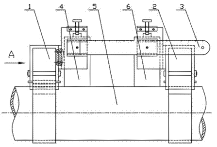
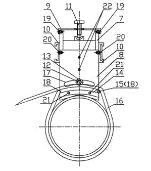
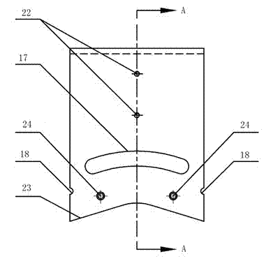
[0037] Figure 1~ Figure 14As shown, the device includes: a set of (two identical) probe fixtures 1, 2, and a set of clamp-on probes 4, 6 installed on the probe fixtures 1, 2. The probe fixtures 1 and 2 include a probe guide frame 7, a support frame 8 and a probe pressing device. Wherein, the probe guide frame 7 in the single probe fixture 4 coincides with the central axis surface of the support frame 8, and two pieces of frame connecting screws 22 are screwed into the through holes 31 on the top 35 of the probe guide frame 7 into the side 26 of the support frame 8. Threaded holes 27 to fasten the two together. The inner distance between the two sides of the probe guide frame 7 is the same as the width of the prob...


PUM


Abstract

The invention discloses a device for installing externally-clamping probes of a portable ultrasonic flow meter. The device comprises a pair of externally-clamping probes which are arranged on a pair of probe fixtures, wherein each probe fixture is arranged on the outer wall of a pipeline to be detected through a fixture fixing device; the middle shaft surface of each probe fixture and the axis ofthe pipeline to be detected are adjusted to be on the same plane by an adjusting device; each probe fixture comprises a support frame, a probe guide frame and a probe pressing device; the support frame and the middle shaft surface in the probe guide frame are overlapped and fastened together; an inner side gap between two sides of the probe guide frame is the same as the width of the probe, so that the middle shaft surface of the probe is automatically overlapped with the middle shaft surface of the probe guide frame, namely is overlapped with the middle shaft surface of the probe fixture, after the probe is guided into the probe guide frame; and the probe pressing device presses the probe to make the probe tightly attached to the outer wall of the pipeline to be detected. By the installation device, the probes can be accurately and conveniently positioned; and the device is easy and convenient to carry and install.

Description

technical field [0001] The invention relates to the field of pipeline flow measurement, in particular to an installation device for an external clip-on probe of a portable ultrasonic flowmeter. Background technique [0002] To use the clamp-on probe of the ultrasonic flowmeter to sense the flow in the pipeline, it is necessary to install the two probes of the ultrasonic flowmeter close to the pipeline, and keep the central axis of the two probes and the axis of the pipeline under test in the same plane. In addition, to make the probes in an ideal working state, the relative distance between the two probes should also be controlled. After analyzing the existing technical literature, "Problems that should be paid attention to in the installation of ultrasonic flowmeters" (Industrial Metrology, 2004, 14 (5): 55) provides an installation method for the clamp-on probe of ultrasonic flowmeters: Coordinate installation method, that is, firstly fix the position of a probe, use a p...

Claims


Application Information

Patent Timeline
Patent Type & Authority Applications(China)
IPC IPC(8): G01F1/66
Inventor 陶建峰危尊豪刘成良顾建江黄健方海珍邱坤贤虞祖艺
Owner SHANGHAI JIAO TONG UNIV
Learn More