Double-high and low voltage on-load regulating transformer

A voltage regulating transformer and dual high voltage technology, applied in the field of transformer manufacturing, can solve the problems of high cost, complex structure, unsuitable voltage level of dual high voltage transformers, etc., and achieve the effect of cost saving and low cost

Inactive Publication Date: 2012-02-22
SANBIAN SCI TECH
View PDF5 Cites 10 Cited by
  • Summary
  • Abstract
  • Description
  • Claims
  • Application Information

AI Technical Summary

Problems solved by technology

It consists of a main transformer consisting of a high-voltage coil and a low-voltage coil, a voltage regulating coil, a reactive switch, a reactor, and a voltage regulating transformer composed of a parallel coil and a series coil; a regulator is set between the low-voltage coil and the iron core of the main transformer. Voltage regulating coil, the voltage regulating coil is set on the iron core of the main transformer; The contacts of the switch are connected; the primary side parallel coil of the voltage regulating transformer is connected in parallel with the voltage regulating coil of the main transformer; the secondary side series coil of the voltage regulating transformer is connected in series with the low voltage coil of the main transformer, but the system structure is complex and higher cost
[0005] The above-mentioned two kinds of transformers are distribution transformers, and the low-voltage on-load tap-changing transformer is difficult to match the switching current with the low-voltage rated current, so the design requires a large-current reactance switch, a built-in reactor and a series tap-changing transformer. In this way, the required cost will be relatively high, and the voltage level used by its double high-voltage transformer is not suitable for the application of 72KV and 138KV in the North American market

Method used


Image

  • Double-high and low voltage on-load regulating transformer
  • Double-high and low voltage on-load regulating transformer
  • Double-high and low voltage on-load regulating transformer

Examples


Embodiment Construction

[0023] The following are specific embodiments of the present invention combined with the accompanying drawings to further describe the technical solutions of the present invention, but the present invention is not limited to these embodiments.

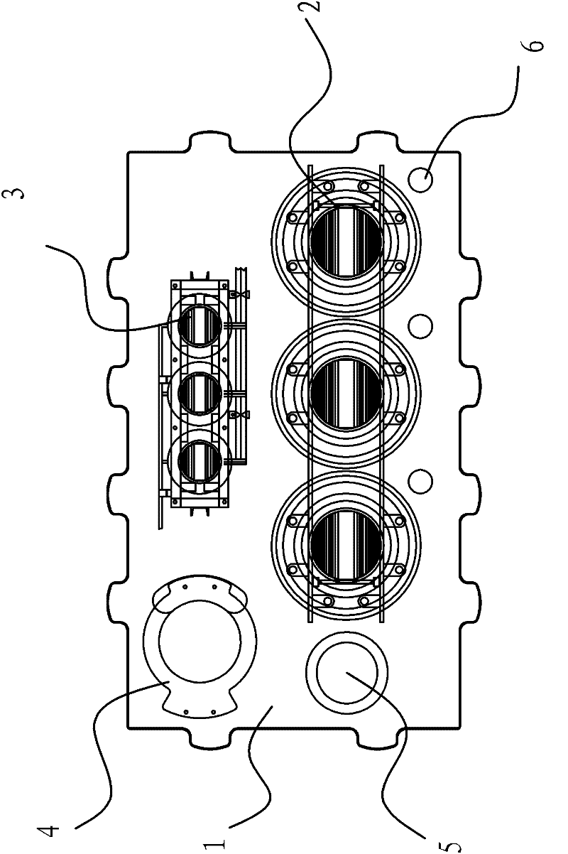
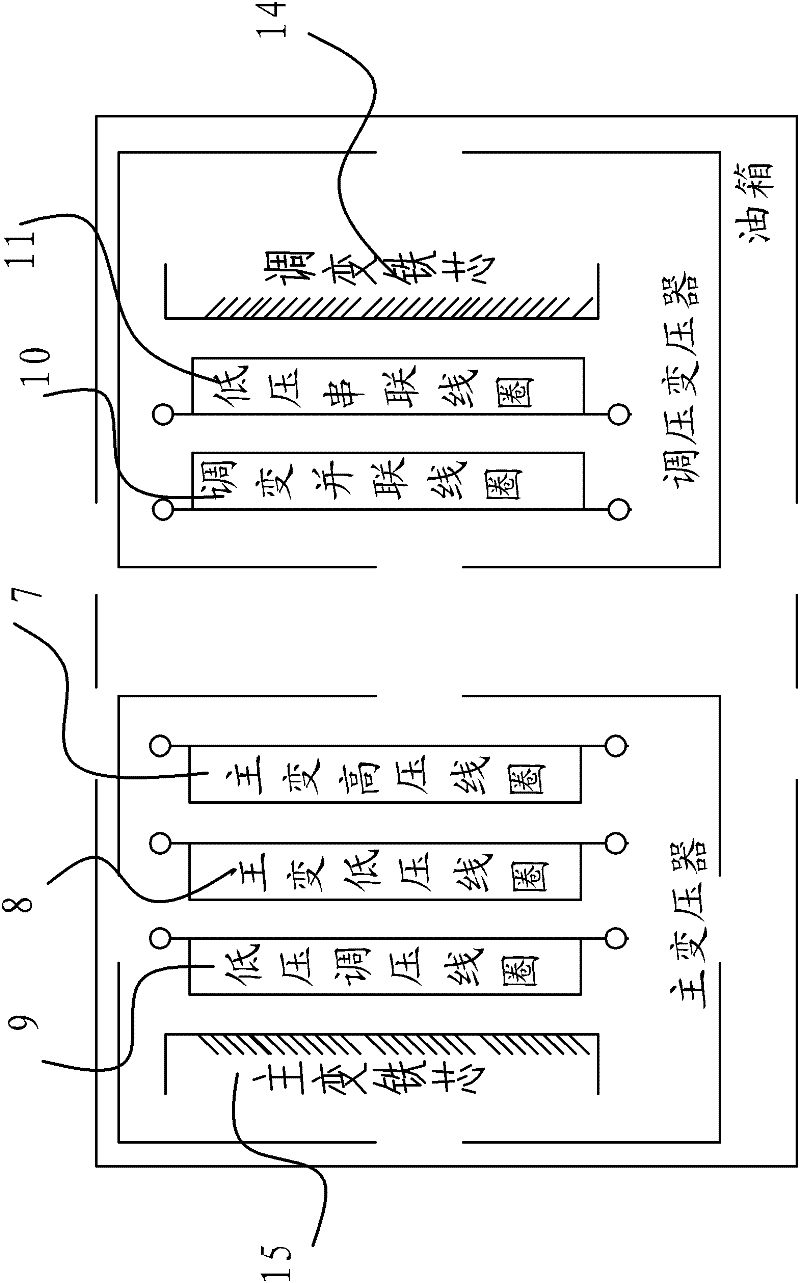
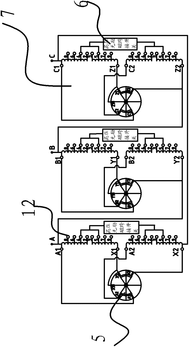
[0024] Such as figure 1 , 2 , 3, and 4, the dual high-voltage and low-voltage on-load tapping transformer includes an oil tank 1, a main transformer 2 and a tapping transformer 3 arranged in the oil tank 1. The main transformer 2 and tapping transformer 3 share the same oil tank 1. The oil tank 1 is also provided with a low-voltage on-load voltage regulating switch 4, a high-voltage serial-to-parallel conversion switch 5, and a high-voltage non-excitation tap switch 6. The main transformer 2 includes a main transformer core. The main transformer high-voltage coil 7, the main transformer low-voltage coil 8 and the low-voltage regulating coil 9 are sequentially arranged on the main transformer core from outside to inside. The regulating tran...


PUM


Abstract

The invention provides a double-high and low voltage on-load regulating transformer, which belongs to the technical field of transformer manufacturing and solves the problem that the voltage class in the prior art is not suitable for the application of 72KV and 138KV in North American markets. A system comprises an oil tank, a main transformer and a regulating transformer, wherein the main transformer and the regulating transformer are arranged in the oil tank; the main transformer comprises a main transformer core; the main transformer core is provided with a main transformer high-voltage coil, a main transformer low-voltage coil and a low-voltage regulating coil from outside to inside in sequence; the main transformer high-voltage coil is divided into two branch coils which are connected through a high-voltage serial parallel switch; the regulating transformer comprises a regulating transformer core; the regulating transformer core is provided with a regulating transformer parallel coil and a low-voltage serial coil from outside to inside in sequence; the low-voltage serial coil of the regulating transformer is connected in series with the main transformer low-voltage coil; and the regulating transformer parallel coil of the regulating transformer and the low-voltage regulating transformer coil are connected in parallel through a low-voltage on-load regulating switch. The system can be suitable for two different voltage classes, and can also simplify traditional structures and reduce the cost.

Description

Technical field [0001] The invention belongs to the technical field of transformer manufacturing, and relates to a dual high-voltage and low-voltage on-load tapping transformer. Background technique [0002] A general power transformer is composed of a low-voltage coil and a high-voltage coil. With the development of society and economy, people have put forward some special requirements for electricity usage and power supply lines. It is hoped that the incoming line voltage can vary from different voltage levels at different time periods. In the past, power transformers can only handle lines of one voltage level. If you want to input lines of two voltage levels, you need two power transformers to achieve this. This makes it inconvenient and costly for people to use. North American power users are different from the requirements of domestic power users. They are accustomed to using on-load voltage regulation on the low-voltage side of power transformers to adjust line voltage fluc...

Claims


Application Information

Patent Timeline
Patent Type & Authority Applications(China)
IPC IPC(8): H01F29/04H01F27/28H01H1/56
Inventor 徐秋元
Owner SANBIAN SCI TECH
Why Eureka
Try Eureka