Reconfigurable antenna adopting reed pipe

A technology for reconstructing antennas and reed switches, which is applied in the field of antenna design and can solve problems such as the influence of antenna radiation performance

Inactive Publication Date: 2012-02-22
NORTHWESTERN POLYTECHNICAL UNIV
View PDF3 Cites 2 Cited by
  • Summary
  • Abstract
  • Description
  • Claims
  • Application Information

AI Technical Summary

Problems solved by technology

Since the DC control circuit is directly connected to the antenna, it will inevitably affect the radiation performance of the antenna

Method used


Image

  • Reconfigurable antenna adopting reed pipe
  • Reconfigurable antenna adopting reed pipe
  • Reconfigurable antenna adopting reed pipe

Examples


Embodiment Construction

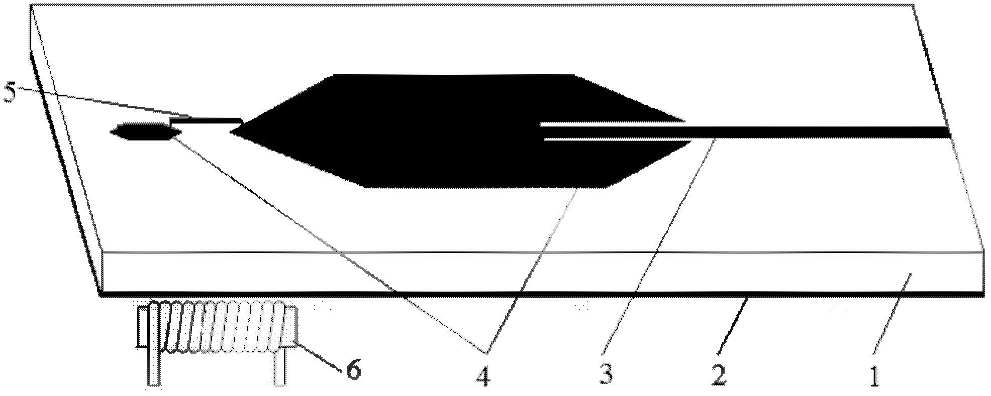
[0012] refer to figure 1 , the present invention consists of a dielectric substrate 1, an antenna ground plane 2, a microstrip feeder 3, a microstrip patch 4, a reed switch 5 and a control coil 6.

[0013] The dielectric substrate 1 of the reconfigurable antenna using a reed switch is a double-layer copper clad laminate, the lower surface of the dielectric substrate 1 is the antenna ground plane 2, and the upper surface is a microstrip feeder 3, two microstrips patch 4. Two microstrip patches 4 are connected by a reed switch 5, and the microstrip feeder 3 goes deep into one microstrip patch 4 to achieve impedance matching of the antenna, and the depth is determined by the impedance of the antenna. The control coil 6 is a DC control circuit, placed under the ground plane 2 of the antenna, directly below the reed switch 5 , and the axis of the control coil 6 is parallel to the reed switch 5 .

[0014] When a current passes through the control coil 6, a magnetic field will be g...


PUM


Abstract

The invention discloses a reconfigurable antenna adopting a reed pipe. The lower surface of a medium substrate is an antenna horizontal plane, and the upper surface of the medium substrate is provided with a microstrip feeder line and a plurality of microstrip patches; the microstrip feeder line extends into one microstrip patch so as to realize impedance matching of the antenna; the microstrip patches are connected by the reed pipe; a control coil is a direct-current control circuit, is placed below the antenna horizontal plane and is positioned right below the reed pipe, and the axis of the control coil is parallel to the reed pipe. In the reconfigurable antenna, the reed pipe is adopted as a magnetic control switch, the control coil is placed below the antenna horizontal plane, and the control magnetic field generated by the control coil can penetrate through the antenna horizontal plane to control the reed pipe, so that the control coil can not cause influence on the radiating performance of the antenna.

Description

technical field [0001] The invention belongs to the technical field of antenna design and relates to a reconfigurable antenna. Background technique [0002] With the rapid development of wireless communication technology, people hope that one antenna can work in multiple different frequency bands. One solution is to use ultra-wideband antennas or multi-band antennas, which can cover multiple frequency bands. Another solution is to use a reconfigurable antenna, which can be time-divisionally tuned to different operating frequency bands as required. [0003] A commonly used method for implementing a reconfigurable antenna is to use a PIN diode or a MEMS switch to connect or disconnect a conductive path on the antenna, so as to change the geometric shape of the antenna, and then change the operating frequency of the antenna. For example, the literature "Pattern and frequency reconfigurable annular slot antenna using PIN diodes, S.Nikolaou, R.Bairavosubramanian, C.Lugo Jr., I....

Claims


Application Information

Patent Timeline
Patent Type & Authority Applications(China)
IPC IPC(8): H01Q1/38
Inventor 吴昌英王婷任安康李建周
Owner NORTHWESTERN POLYTECHNICAL UNIV
Why Eureka
Try Eureka