Barrier-free automatic lifting speed bump and control method

A technology of automatic lifting and speed bumps, applied in the directions of roads, road signs, traffic signals, etc., can solve the problems of reverse vehicle driving obstacles, tire and body damage, impact speed bumps, etc., so as to reduce maintenance costs and improve driving safety. , the effect of prolonging tire life

Inactive Publication Date: 2012-02-29
CIVIL AVIATION UNIV OF CHINA
View PDF8 Cites 33 Cited by
  • Summary
  • Abstract
  • Description
  • Claims
  • Application Information

AI Technical Summary

Problems solved by technology

Although setting speed bumps can reduce the occurrence of traffic accidents to a large extent, there are still many problems, such as: the expansion screws left on the road after the speed bumps are damaged are likely to puncture the car tires, causing the vehicle to lose control; the noise of vehicle bumps Seriously interfered with the lives of the surrounding residents; the existing speed bumps cannot distinguish between motor vehicles and non-motor vehicles, so it is very easy to cause non-motor vehicles to skid in ice and snow weather; and personnel comfort; the existing speed bumps cannot reflect the principle of "rewarding slow and punishing fast", that is to say, even if the vehicle is driving at a low speed, it will still hit the speed bump, thus causing damage to the tires and the car body
[0003] In view of the above problems, relevant scholars have carried out a certain degree of research. Chinese patent applications No. 200720021665.6, 200720174551.5, 201120018191.6, 201120103041.5 and 201010261228.8 respectively disclose th

Method used


Image

  • Barrier-free automatic lifting speed bump and control method
  • Barrier-free automatic lifting speed bump and control method
  • Barrier-free automatic lifting speed bump and control method

Examples


Embodiment Construction

[0029] The barrier-free automatic lifting deceleration belt and the control method provided by the present invention will be described in detail below in conjunction with the accompanying drawings and specific embodiments.

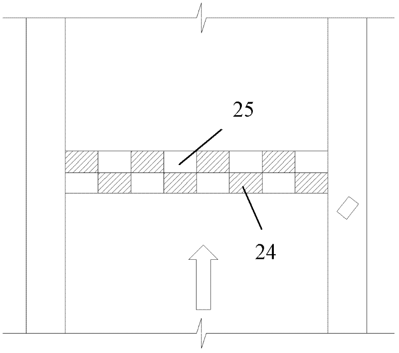
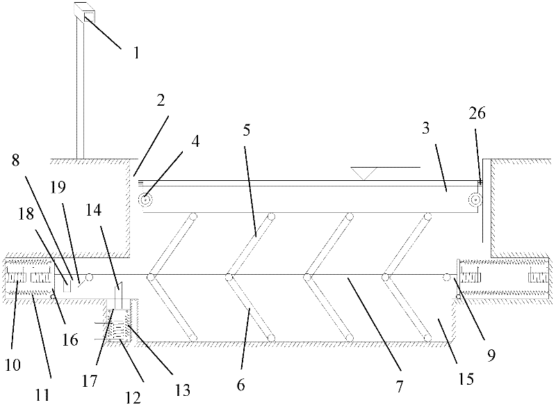
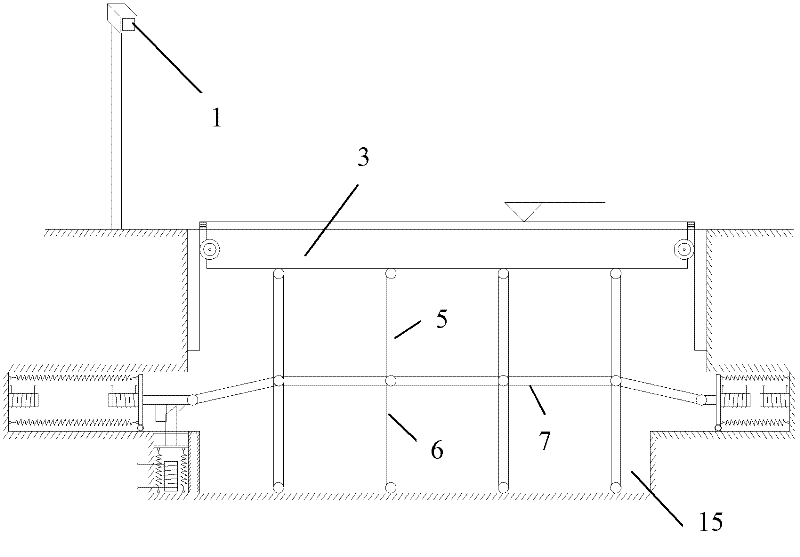
[0030] Such as Figure 1-Figure 5As shown, the barrier-free automatic lifting deceleration belt provided by the present invention includes a radar speedometer 1, four guide rails 2, a deceleration plate 3, four sliding wheels 4, a plurality of upper support rods 5, a plurality of lower support rods 6, a plurality of Contact rod 7, left push-pull rod 8, right push-pull rod 9, two groups of push-pull electromagnets 10, multiple push-pull springs 11, thrust electromagnet 12, multiple thrust springs 13, thrust rod 14 and control device; Wherein radar velocimeter 1 is arranged on the roadside, is used to detect the speed of traveling vehicle; Four guide rails 2 are divided into two groups and are vertically installed on the two sidewalls of the strip foundation...


PUM


Abstract

The invention discloses a barrier-free automatic lifting speed bump and a control method. The speed bump comprises a radar speed indicator, four guide rails, a speed reducing plate, four sliding wheels, a plurality of upper supporting rods, a plurality of lower supporting rods, a plurality of link rods, a left push-pull rod, a right push-pull rod, two groups of push-pull electromagnets, a plurality of push-pull springs, a thrust electromagnet, a plurality of thrust springs, a thrust rod and a control device. The barrier-free automatic lifting speed bump has no barrier to the normal running vehicles, and can forcibly decelerate the over-speed vehicles, so that the road running comfortableness and the running safety can be improved, the noise is reduced, the service life of a tyre is prolonged and the overhauling expense is reduced. In addition, the control method is simple and convenient.

Description

technical field [0001] The invention relates to a speed limiting device for road vehicles, in particular to a barrier-free automatic lifting deceleration belt and a control method. Background technique [0002] At present, the speed bumps installed on the road are all strips, dots or block structures directly fixed on the road surface, the purpose is to force motor vehicles to slow down, so as to ensure that traffic participants pass through crossings, schools, houses and accident-prone roads. life safety. Although setting speed bumps can reduce the occurrence of traffic accidents to a large extent, there are still many problems, such as: the expansion screws left on the road after the speed bumps are damaged are likely to puncture the car tires, causing the vehicle to lose control; the noise of vehicle bumps Seriously interfered with the lives of the surrounding residents; the existing speed bumps cannot distinguish between motor vehicles and non-motor vehicles, so it is v...

Claims


Application Information

Patent Timeline
IPC IPC(8): E01F9/047E01F9/529
Inventor 刘国光张献民解本铭赵方冉程国勇武志玮马龙敖士楷蔡锋冯恩龙李金泽梁将兵谭振王涛许涛姚书广章彦
Owner CIVIL AVIATION UNIV OF CHINA
Why Eureka
Try Eureka