
High-ductility steel structure beam column node in angle steel connection and construction method of high-ductility steel structure beam column node

A beam-column joint and steel structure technology, which is applied to building components, building structures, and building materials processing, etc., can solve problems such as welding brittle failure of steel beam roots and steel columns, and achieve convenient construction, simple and fast repair work, Inexpensive repairs

Active Publication Date: 2012-02-29
FUZHOU UNIV
View PDF7 Cites 51 Cited by
  • Summary
  • Abstract
  • Description
  • Claims
  • Application Information

AI Technical Summary

Problems solved by technology

The oblong hole of this node is set at the joint of the steel beam flange and the web, and the connection between the steel beam root and the steel column is still connected by a weld. Therefore, under the action of a rare earthquake, when the rotation range of the steel beam joint exceeds its At the limit of rotation capacity, it is still possible to cause welding brittle failure at the root of the steel beam and the steel column

Method used


Image

  • High-ductility steel structure beam column node in angle steel connection and construction method of high-ductility steel structure beam column node
  • High-ductility steel structure beam column node in angle steel connection and construction method of high-ductility steel structure beam column node
  • High-ductility steel structure beam column node in angle steel connection and construction method of high-ductility steel structure beam column node

Examples


Embodiment Construction

[0034] In order to make the above-mentioned features and advantages of the present invention more comprehensible, the following specific embodiments are described in detail with reference to the accompanying drawings.

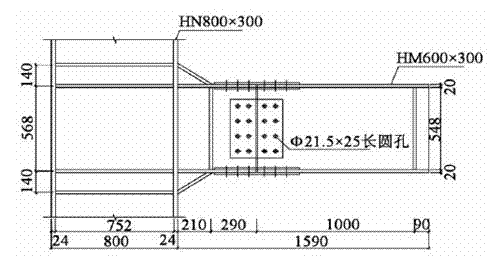
[0035] as attached Figure 4As shown, a beam-column node of a high ductility steel structure connected by angle steel in the present invention includes a steel column 1 and an H-shaped steel beam 2, a flange angle steel 3, a web angle steel 5, a flange steel backing plate 4, and a web Steel backing plate 6, horizontal stiffener 8 and several friction-type high-strength bolts 7, characterized in that: the upper and lower flange plates of the H-shaped steel beam 2 pass through the flange angle steel 3, the flange steel backing plate 4 and the Friction-type high-strength bolts 7 are connected to the steel column 1, and the web of the H-shaped steel beam 2 is connected to the steel column 1 through the web angle steel 5, the web steel backing plate 6 and the fricti...


PUM


Abstract

The invention relates to a high-ductility steel structure beam column node in angle steel connection and a construction method of the high-ductility steel structure beam column node. The invention is characterized in that: upper and lower flange plates of an H-shaped steel beam are respectively connected with a steel column by using flange angle steel, a flange steel cushion plate and a friction type high-strength bolt; a web plate of the H-shaped steel beam is connected with the steel column by using web plate angle steel, a web plate steel cushion plate and the friction type high-strength bolt; bolt holes in a flange angle steel branch and a web plate angle steel branch, which are connected with the H-shaped steel beam, are long circular holes; horizontal reinforcing ribs are arranged, at a joint of the steel column and the H-shaped steel beam, inside the steel column; and a gap is reserved between an end head of the H-shaped steel beam and the steel column. The high-ductility steel structure beam column node has quite high ductile deformation capacity and excellent energy-dissipation capacity; and connection welded beams are not formed on beam column members, so that the brittle failure of the steel beam or the steel column in a node area under the action of a seldom-occurring earthquake is avoided. Furthermore, the high-ductility steel structure beam column node has the advantages of convenience for construction, simple and quick in repair operation after the earthquake, low in repair cost and the like.

Description

technical field [0001] The invention relates to the technical field of civil engineering, in particular to a beam-column node of a high-ductility steel structure connected by angle steel and a construction method thereof. Background technique [0002] Good ductility is the key factor to ensure that the structure does not collapse under strong earthquakes, and the ductility of joints is a key factor affecting the overall ductility of the structure. Before the Northridge (Northridge) earthquake in the United States in 1994, bolted and welded connections (flange welding, web bolted connections) were commonly used forms of beam-to-column connections in steel frame structures. However, in the Northridge (Northridge) earthquake in the United States in 1994 and the Hanshin earthquake in Japan in 1995, the steel frame that was once considered to have good seismic performance suffered a lot of damage, most of which were caused by beam-column bolted joints. Brittle fracture (that is,...

Claims


Application Information

Patent Timeline
Patent Type & Authority Applications(China)
IPC IPC(8): E04B1/58E04B1/98E04G21/14
Inventor 黄冀卓陈宝春
Owner FUZHOU UNIV
Learn More