
Reaming bonded reinforced casing type FRP structure beam-column node

A technology of beam-column joints and sleeves, applied in the direction of building components, building types, building structures, etc., can solve the problems of insufficient ductility and easy brittle failure, and achieve the effect of improving ductility, avoiding brittle failure, and slim shape

Pending Publication Date: 2019-10-22
NANHUA UNIV
View PDF9 Cites 0 Cited by
  • Summary
  • Abstract
  • Description
  • Claims
  • Application Information

AI Technical Summary

Problems solved by technology

[0005] For high-intensity fortified earthquake areas, Professor Huang Jizhuo of Fuzhou University has applied for and obtained patents (Patent No.: 201020181041.2, 201010164386.1) which disclose a new type of easily repairable steel structure beam-column joint, which can better solve the traditional beam-column connection The joints have insufficient ductility and are prone to brittle failure, and they are easy to repair after the earthquake; the easy-to-repair steel structure beam-column joints have semi-rigid joints, and their ductility and energy dissipation capacity are further improved. FRP frame beam-column joints are also a kind of Semi-rigid joints have the conditions to adopt high-strength friction bolts with oblong holes. Therefore, on the basis of semi-rigid bolt connections, an FRP structural beam-column joint with better ductility and energy dissipation capacity is invented.

Method used


Image

  • Reaming bonded reinforced casing type FRP structure beam-column node
  • Reaming bonded reinforced casing type FRP structure beam-column node
  • Reaming bonded reinforced casing type FRP structure beam-column node

Examples


Embodiment

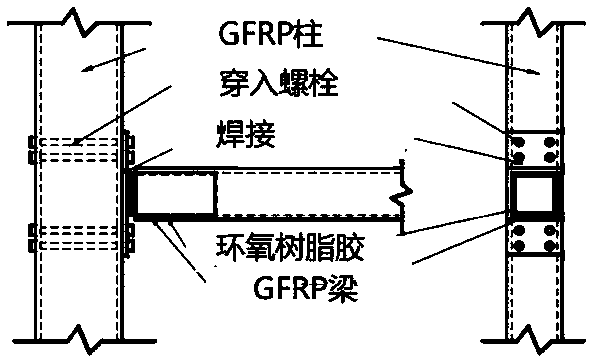
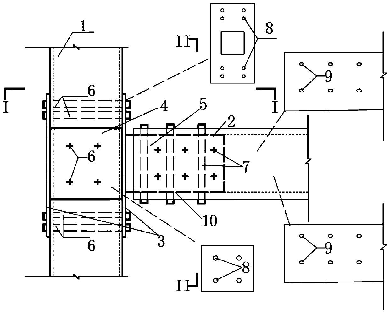
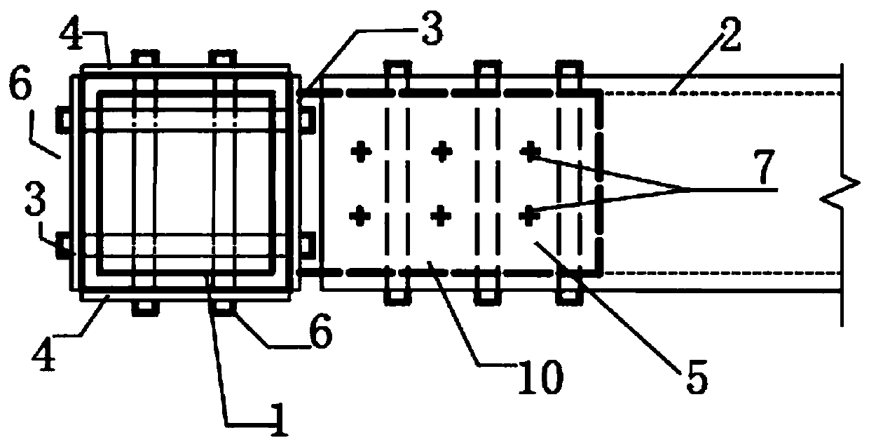
[0040] See Figure 2-6 , A reamed and glued reinforced casing FRP structural beam-column node, including FRP column 1, FRP beam 2, end plate 3, side plate 4, casing 5, high-strength penetration bolt 6, high-strength friction bolt 7, Ordinary bolt hole 8, oblong bolt hole 9 and epoxy resin 10, FRP column 1 is a square hollow FRP column, FRP beam 2 is a square hollow FRP beam, end plate 3 is provided with a pair, and a pair of end plates 3 are respectively Connected to the left and right sides of the FRP column 1, the left and right sides of the FRP column 1 and a pair of end plates 3 are provided with four pairs of ordinary bolt holes 8, six pairs of high-strength penetration bolts 6, and four pairs of high-strength penetration The bolts 6 are respectively threadedly connected between the four pairs of ordinary bolt holes 8. A pair of end plates 3 are connected to the FRP column 1 by multiple pairs of high-strength penetration bolts 6 and the connection is firm. The side plate 4...


PUM


Abstract

The invention discloses a reaming bonded reinforced casing type FRP structure beam-column node, and belongs to the technical field of civil constructions. The reaming bonded reinforced casing type FRPstructure beam-column node comprises a FRP column, a FRP beam, end plates, side plates, sleeves, high-strength penetration bolts, high-strength friction type bolts, common bolt holes, oblong bolt holes and epoxy resin glue; the one pair of end plates are arranged and respectively connected to the left side and the right side of the FRP column; the four pairs of common bolt holes are formed in theleft side and the right side of the FRP column and the pair of the end plates; the six pairs of high-strength penetration bolts are arranged; the four pairs of the high-strength penetration bolts arerespectively in threaded connection between the four pairs of common bolt holes; the one pair of the side plates are arranged and respectively connected to the front side and the rear side of the FRPcolumn; the two pairs of common bolt holes are formed in the front side and the rear side of the FRP column and the one pair of the side plates; and the other two pairs of the high-strength penetration bolts are connected between the two pairs of common bolt holes. The reaming bonded reinforced casing type beam-column node has strong ductility deformation capacity and good energy dissipation capacity, and can prevent the FRP beam or the FRP column from brittle failure in a node area under the action of a rare occurrence earthquake.

Description

Technical field [0001] The present invention relates to the technical field of civil engineering and construction, and more specifically, to a beam-column node of an FRP structure with a reaming and glued joint reinforcement. Background technique [0002] FRP (fiber reinforced composite material) is a new type of high-performance engineering material that has been successfully applied in civil engineering structures in recent years. It has the advantages of light weight, high strength, corrosion resistance, and convenient construction and molding. It has become a traditional concrete, steel, etc. As an important supplement to structural materials, the rational application of FRP to various structures has become an important direction for the application and development of engineering structures. [0003] Although most of the current FRP research focuses on the repair of existing projects, the seismic reinforcement of structures, the pavement of bridge decks, etc., with the commerci...

Claims


Application Information

Patent Timeline
Patent Type & Authority Applications(China)
IPC IPC(8): E04B1/28E04B1/58E04B1/98E04H9/02
CPCE04B1/185E04B1/28E04H9/021
Inventor 肖潇刘嫦娥王沿尹向东
Owner NANHUA UNIV
Learn More