SRC shear walls constrained by steel sleeves at the root regions at both ends

A technology of concrete shear wall and root area, applied in the direction of walls, buildings, building components, etc., can solve the problems of poor seismic performance, brittle failure, etc., to improve the ductile deformation ability, improve the bending deformation ability, and coordinate the deformation. Effect

Active Publication Date: 2018-01-02
CHONGQING UNIV
View PDF7 Cites 0 Cited by
  • Summary
  • Abstract
  • Description
  • Claims
  • Application Information

AI Technical Summary

Problems solved by technology

Ordinary reinforced concrete medium-high shear walls with straight cross-sections tend to produce oblique cracks in the web area under vertical pressure and horizontal loads, and the crushing and spalling of concrete near the oblique cracks in the web under reciprocating loads lead to brittle failure. The shear failure mode makes This type of wall exhibits poor seismic performance

Method used


Image

  • SRC shear walls constrained by steel sleeves at the root regions at both ends
  • SRC shear walls constrained by steel sleeves at the root regions at both ends
  • SRC shear walls constrained by steel sleeves at the root regions at both ends

Examples


Embodiment Construction

[0020] The present invention is described in detail below in conjunction with accompanying drawing:

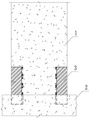
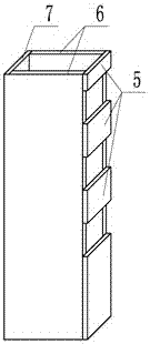
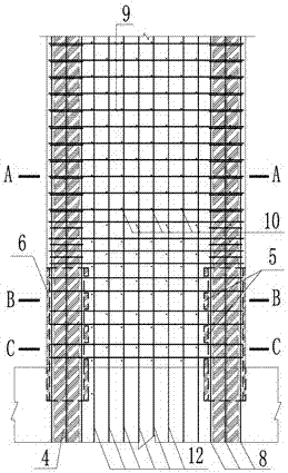
[0021] Such as figure 1 , image 3 as well as Figure 4A , Figure 4B and Figure 4C As shown, the steel sleeve of the present invention constrains the steel concrete shear wall in the root region of both ends to be composed of a concrete wall 1, a wall foundation 2, a steel sleeve 3, a vertical section steel 4 in the hidden column area at the end of the wall, and a hidden column area. The longitudinal reinforcement 8 and the stirrup 11, the web distribution transverse reinforcement 9 and the longitudinal reinforcement 12 are composed.

[0022] Steel sleeves 3 are provided at both ends of the steel concrete shear wall close to the root of the section steel 4 to form a restraint area for the concrete at the bottom of both ends of the wall 1; the bottom of the steel sleeve 3 extends into the wall foundation 2, and the length of the extension is One-half the thickness of the...


PUM


Abstract

The invention provides a profile-steel concrete shear wall with two end root areas restrained by steel sleeves. The steel sleeves are respectively arranged on two ends of the shear wall to be close to the root part of profile steel, wherein the steel sleeves form constraint areas for concrete at the bottom at two ends of a wall body, the root part of the profile steel is disposed in the concrete of the constraint area, and the lateral constraint effect improves the limit compressive strength and limit compressive strain of the concrete, so that the integral bending deformation capacity of the shear wall can be improved. The bottom of each steel sleeve stretches into the foundation of the wall body, and the stretching length is about half of the thickness of the wall body, so that the anti-shear capacity of the wall body is improved, and the root part of the wall body is prevented from being damaged due to penetrating shear. The part, stretching into the foundation, of each steel sleeve can be isolated from the peripheral concrete by utilizing oil paper and the like, so that the sleeves are prevented from being pulled, and the deformation capacity of the profile steel at the pulled side is prevented from being influenced. The profile-steel concrete shear wall has the characteristics of convenience in construction, high anti-seismic capacity and low cost, and is particularly applicable to the profile-steel concrete medium-high shear wall with a linear section and with vertical profile steel arranged in a concealed column area at the end of the wall.

Description

technical field [0001] The invention relates to a steel concrete shear wall and belongs to the technical field of structural engineering. Background technique [0002] A shear wall is a wall used to bear vertical loads and lateral loads in a building structure. When flanges or exposed columns are not allowed at the end of the wall, an inline wall section is usually used. Ordinary reinforced concrete medium-high shear walls with straight cross-sections tend to produce oblique cracks in the web area under vertical pressure and horizontal loads, and the crushing and spalling of concrete near the oblique cracks in the web under reciprocating loads lead to brittle failure. The shear failure mode makes Such walls exhibit poor seismic performance. In order to improve the seismic performance of ordinary reinforced concrete walls, concealed steel-concrete columns or concrete-filled steel tube columns are arranged on both sides of the shear walls to form a constraint frame. For mid-...

Claims


Application Information

Patent Timeline
Patent Type & Authority Patents(China)
IPC IPC(8): E04B2/56E04B2/58
CPCE04B2/56E04B2/58
Inventor 黄宗明高永傅剑平杨溥周珉
Owner CHONGQING UNIV
Why Eureka
Try Eureka