Motion mechanism for underwater welding robot

A technology of underwater welding and motion mechanism, which is applied in the direction of welding equipment, electrode characteristics, arc welding equipment, etc., and can solve the problems of difficult flexibility and accuracy of the hydraulic mechanism, and the inability to complete automatic tracking welding of the weld seam, etc.

Active Publication Date: 2012-03-07
TSINGHUA UNIV
View PDF7 Cites 4 Cited by
  • Summary
  • Abstract
  • Description
  • Claims
  • Application Information

AI Technical Summary

Problems solved by technology

At present, there is no practical underwater welding robot, and the high precision and sealing requirements of the underwater motion mechanism are one of the main difficulties in the design of underwater welding robots
An existing underwater welding robot experimental platform adopts hydraulic control, which meets

Method used


Image

  • Motion mechanism for underwater welding robot
  • Motion mechanism for underwater welding robot
  • Motion mechanism for underwater welding robot

Examples


Embodiment Construction

[0041] The present invention will be described in more detail below in conjunction with the accompanying drawings.

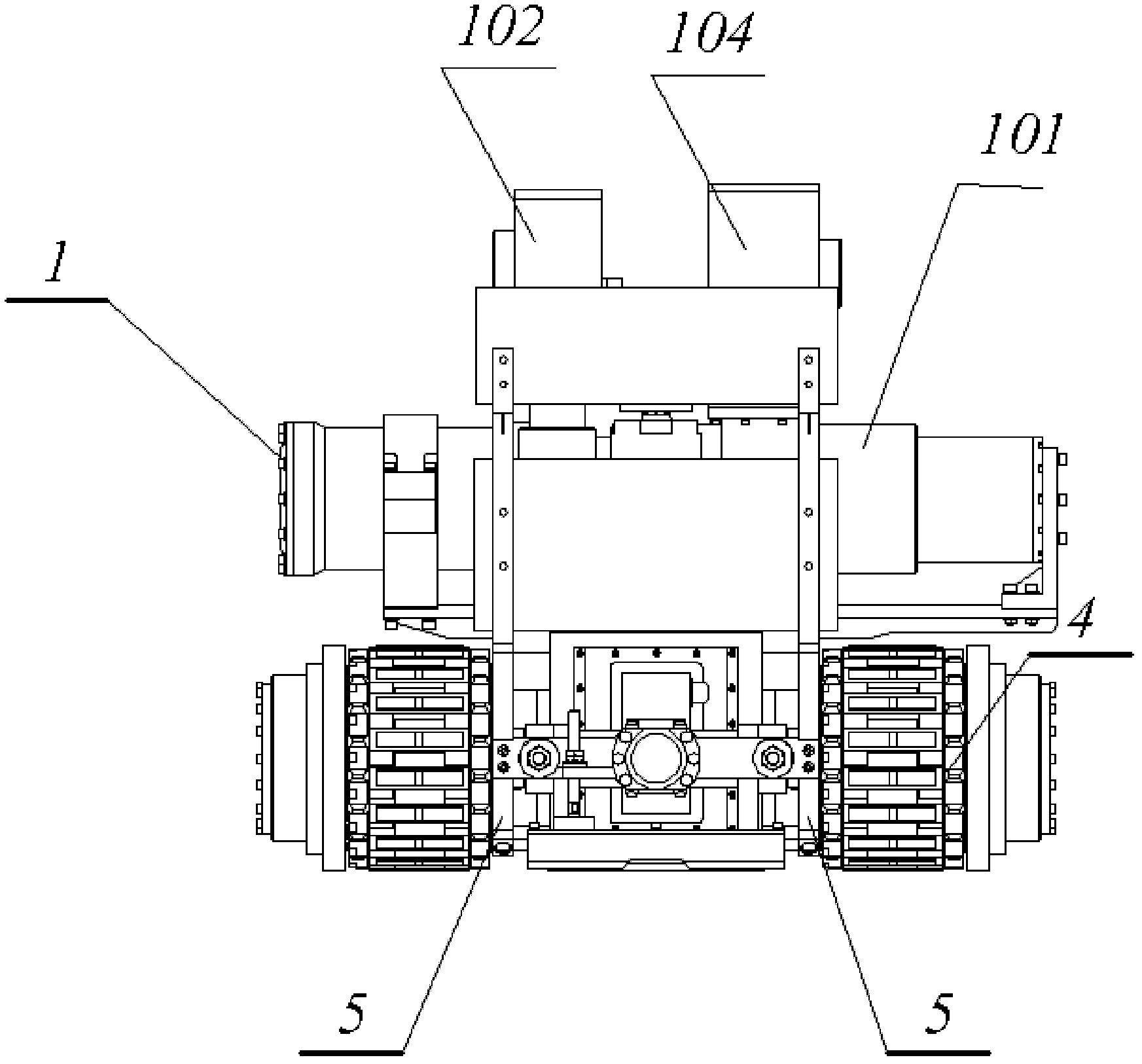
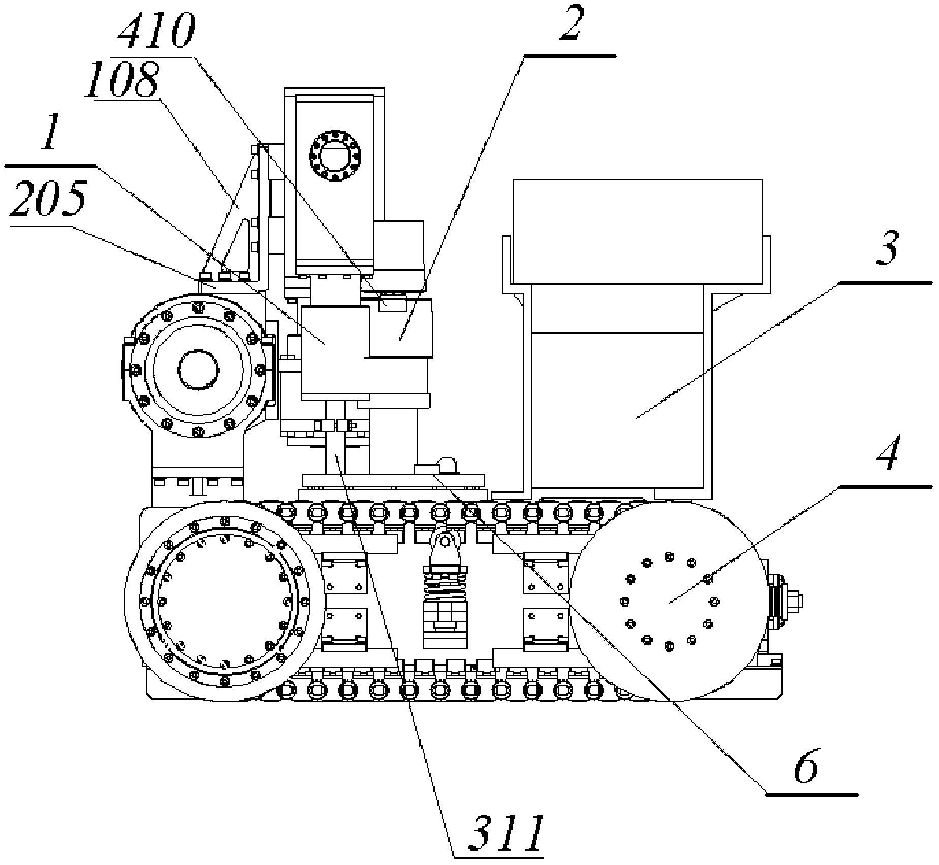
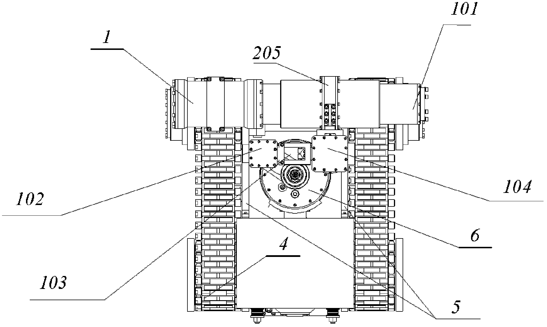
[0042] Such as figure 1 , figure 2 , image 3 , Figure 4 as well as Figure 5 As shown, the kinematic mechanism 1 of the underwater welding robot includes a lateral kinematic mechanism 101 with a lateral kinematic mechanism slider 205, and the lateral kinematic mechanism slider 205 is connected to a right-angled side of a right-angled triangle bracket 108, and the right-angled triangle bracket 108 The other right-angled side and the partial cover pressing mechanism 104 are connected in the vertical direction, and the movable block of the partial cover pressing mechanism 104 is connected with the partial cover 6 of the underwater welding robot through the partial cover connecting rod 311, and the partial cover is pressed in addition. The mechanism 104 is connected with the welding torch adjustment mechanism 102 through the connecting frame 103, the partial ...


PUM


Abstract

The invention discloses a motion robot for a motor-driven underwater welding robot, which comprises three parts, namely a transverse motion mechanism, a local cover hold-down mechanism and a welding gun adjusting mechanism; in addition, static seal is realized by adopting an O-shaped ring and a sealing rubber gasket; move seal is realized by adopting a piston sealing form, so that the motion mechanism accurately and flexibly moves and has reliable sealing performance.

Description

technical field [0001] The invention relates to the technical field of an underwater welding device, in particular to a motion mechanism of an underwater welding robot. Background technique [0002] In the fields of ship repair and maintenance of nuclear power facilities, underwater welding robots are needed to complete welding work that cannot be done directly by humans. Therefore, underwater welding robots have broad application prospects. [0003] At present, the underwater welding robot mainly includes a mobile body, a motion mechanism, a partial cover, a welding torch on the top of the partial cover, a wire reel and a wire feeder consisting of a wire feeding mechanism, a junction box, and an electrical control box. In this way, during the welding process, the mobile body walks along the direction of the welding seam. The welding seam is identified by the laser and camera installed on the partial hood, and the lateral movement of the welding torch and partial hood is co...

Claims


Application Information

Patent Timeline
IPC IPC(8): B23K9/12B23K9/127B23K9/28
Inventor 张伯奇房婷潘际銮
Owner TSINGHUA UNIV
Why Eureka
Try Eureka