Optical link protection switching realizing method in Ethernet passive optical network system

A passive optical network and protection switching technology, applied in the field of Ethernet passive optical network, can solve the problems of long service interruption time, ONU disconnection, standby PON port cannot obtain ONU related information, etc., and achieve good service interruption time performance , the effect of improving compatibility

Active Publication Date: 2014-07-02
FENGHUO COMM SCI & TECH CO LTD +1
View PDF3 Cites 0 Cited by
  • Summary
  • Abstract
  • Description
  • Claims
  • Application Information

AI Technical Summary

Problems solved by technology

[0005] First, the active and standby PON ports have different MPCP (Multiple Point Control Protocol, multi-point control protocol) sublayers, so the MPCP clocks are different, which will cause the time scale of the MPCP frame received by the ONU may change suddenly during the switching process , causing the ONU to go offline. After the ONU goes offline, it needs to re-register, and the interruption time of the switching service is relatively long;
[0006] Second, the main and standby PON ports maintain different ONU status information respectively, and the use of an optical splitter with an optical split ratio of 2:N requires that the laser of the standby PON port be turned off under normal conditions, so the standby PON port cannot pass through the normal way Get information about ONU
Once a switchover occurs, if the standby PON port cannot obtain ONU information quickly, the current state of the system cannot be maintained, resulting in a longer service interruption time;
[0007] Third, in some cases, the length difference between the main trunk fiber and the backup trunk fiber may be large, resulting in a large RTT (Round-Trip Time, round-trip delay) ranging value of all ONUs after the switchover occurs The change of the ONU caused the ONU in normal work to be disconnected and the ONU information of the main and standby PON port of the OLT (Optical Line Tterminal, optical cable terminal equipment) is inconsistent

Method used


Image

  • Optical link protection switching realizing method in Ethernet passive optical network system
  • Optical link protection switching realizing method in Ethernet passive optical network system
  • Optical link protection switching realizing method in Ethernet passive optical network system

Examples


Embodiment Construction

[0027] The present invention will be further described in detail below in conjunction with the accompanying drawings and embodiments.

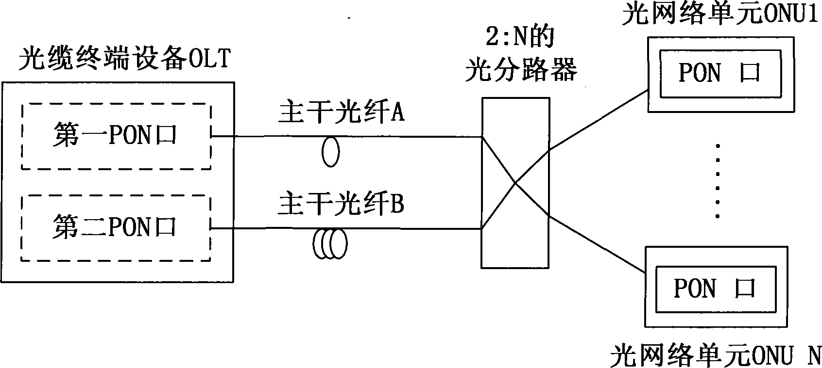
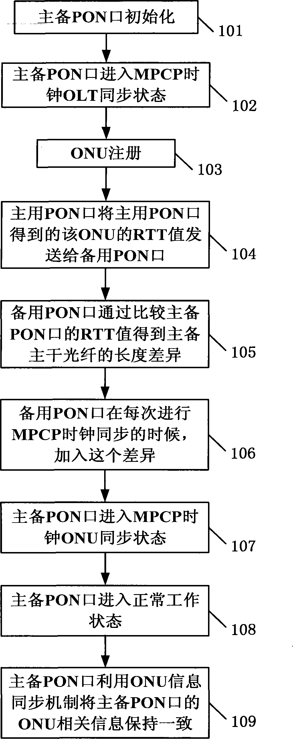
[0028] see figure 2 As shown, the implementation method of optical link protection switching in the Ethernet passive optical network system provided by the embodiment of the present invention specifically includes the following steps:

[0029] Step 101: Initialize the active and standby PON ports.

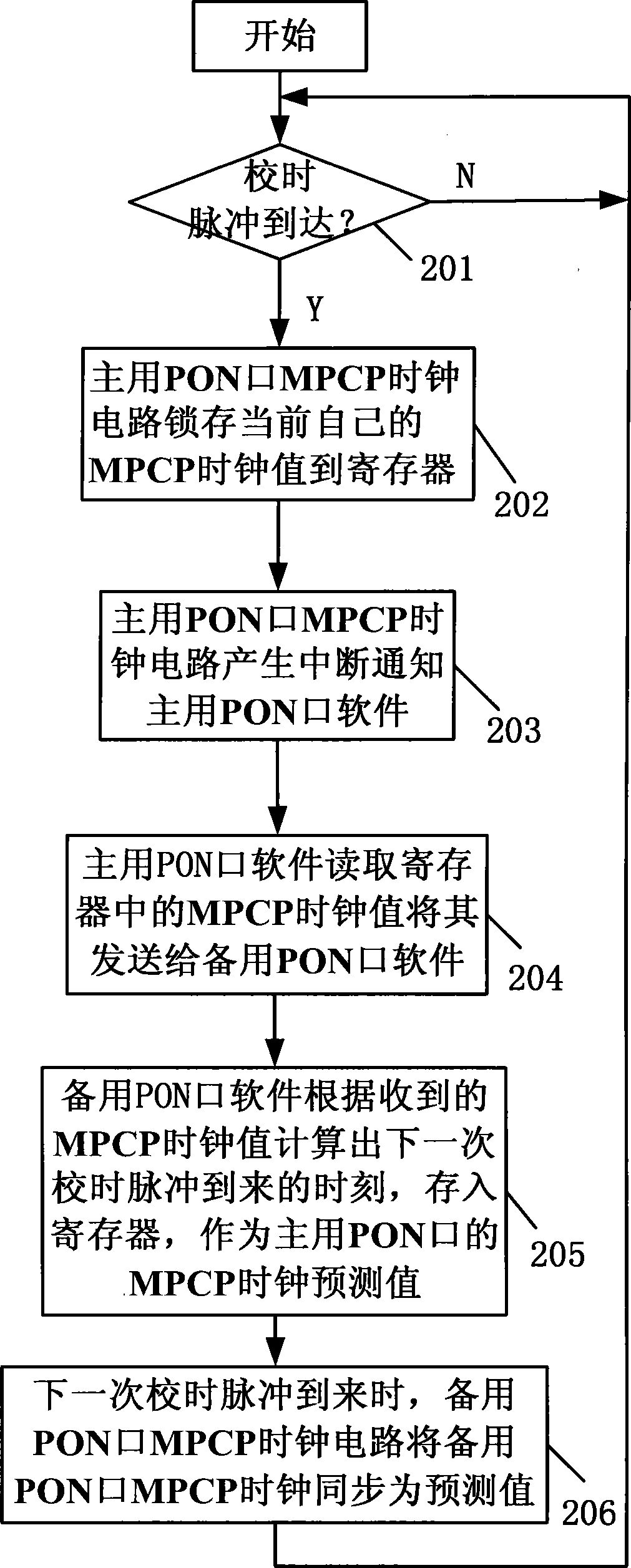
[0030] Step 102: Adjust the MPCP clocks of the active and standby PON ports to be the same through the MPCP clock synchronization mechanism, and the active and standby PON ports enter the MPCP clock OLT synchronization state.

[0031] Step 103: When there is an ONU registered in the EPON system, the MPCP clock adjustment operation in the next step can be performed.

[0032] Step 104: The active PON port sends its round-trip time delay RTT ranging value to the ONU to the standby PON port, and the implementation method is: data transmission is per...


PUM


Abstract

The invention discloses a method for realizing optical link protection switchover in an EPON system, comprising steps: after initialization, the MPCP clocks of the active and standby PONs are adjusted to be the same through the MPCP clock synchronization mechanism, and enter the MPCP clock OLT synchronization state; when the ONU registers, the active The PON sends its RTT value to the ONU to the standby PON. The standby PON compares the RTT values ​​of the active and standby PONs to the same ONU to obtain the length difference between the active and standby trunk fibers, and adjusts the MPCP clocks of the active and standby PONs to maintain a fixed difference. When the PON performs MPCP clock synchronization, it compensates for the difference and enters the MPCP clock ONU synchronization state; after normal operation, use the ONU information synchronization mechanism to keep the ONU-related status information of the active and standby PONs consistent. The invention can ensure that the ONU is not disconnected during the switching process, and has better service interruption time performance, and is suitable for the protection of PON ports in the same PON board and between boards of the OLT.

Description

technical field [0001] The invention relates to an Ethernet passive optical network in the communication field, in particular to a method for realizing optical link protection switching in an Ethernet passive optical network system. Background technique [0002] The rapid development of the Internet has brought about the rapid growth of data services, and the demand for broadband access technology is also getting higher and higher. EPON (Ethernet Passive Optical Network, Ethernet Passive Optical Network) has been widely used due to its advantages of low cost, high reliability, less maintenance, and high bandwidth. ITU-T (International Telecommunication Union Telecommunication Standardization Sector, the International Telecommunication Union's telecommunication standardization sector, responsible for formulating standards in the field of communication) provides two protection switching methods in the G.983.5 proposal on EPON protection: the backbone fiber protection switching...

Claims


Application Information

Patent Timeline
Patent Type & Authority Patents(China)
IPC IPC(8): H04B10/032H04B10/07H04J3/06
Inventor 钟山温玉屏杨志勇张星谢振新
Owner FENGHUO COMM SCI & TECH CO LTD
Why Eureka
Try Eureka