Drive device for driving work unit

A driving device and work unit technology, applied in applications, home appliances, kitchen appliances, etc., can solve the problems of increased storage space and large devices, and achieve the goal of reducing storage space, reducing production costs, and improving application possibilities. Effect

Inactive Publication Date: 2012-03-07
LEIFHEIT
View PDF4 Cites 6 Cited by
  • Summary
  • Abstract
  • Description
  • Claims
  • Application Information

AI Technical Summary

Problems solved by technology

Another disadvantage of this connection is that the devices are relatively large, whereby the storage space required for a single device increases

Method used


Image

  • Drive device for driving work unit
  • Drive device for driving work unit
  • Drive device for driving work unit

Examples


Embodiment Construction

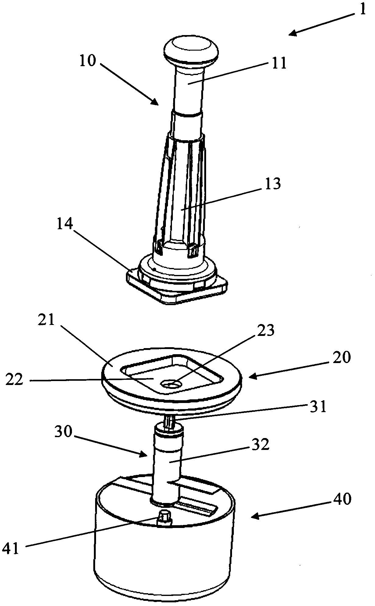
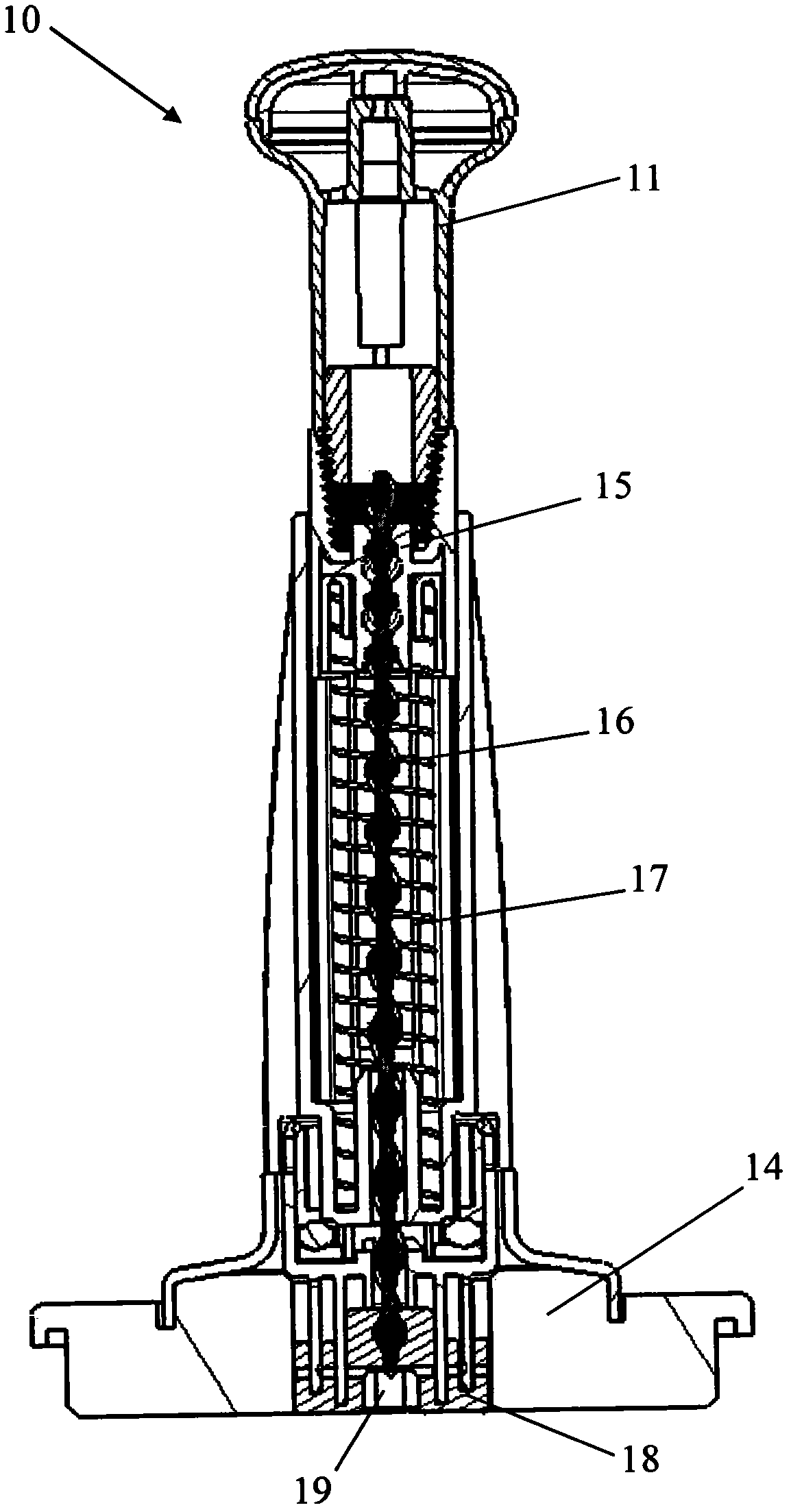
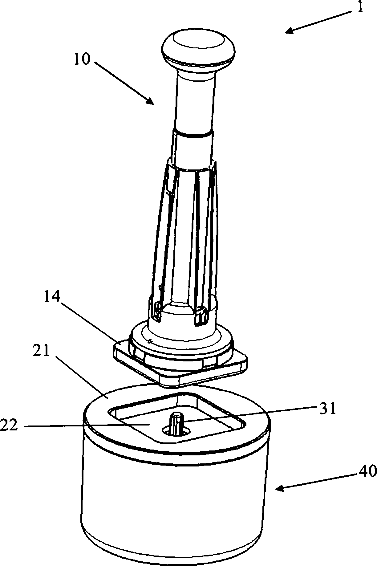
[0015] figure 1 The comminuting device 1 shown in an exploded view has a drive 10 , a partition unit 20 and a container 40 . The drive 10 has a rotationally fixed actuating device 11 , a coupling element 14 and a housing 13 arranged between the actuating device 11 and the coupling element 14 .

[0016] The handling device 11 has the shape of a pestle and is movable along the longitudinal axis of the drive device 10 . When the actuating device 11 is moved, it moves relative to the housing 13 which is immovable in the longitudinal direction. The coupling element 14 is detachably connected to the housing 13 .

[0017] The partition unit 20 has a partition element 21 which closes the container 40 . The separating element 21 has a recess 22 which has the same shape as the coupling element 14 of the drive device 10 . The recess 22 has an opening 23 which is dimensioned such that a coupling device 31 of a working unit 30 can pass through it.

[0018] In addition to the coupling ...


PUM


Abstract

The invention relates to a drive device (10) for driving a work unit (30), which contains grinding elements for food, for example, and a method for driving the work unit. The drive device (10) and the work unit (30) are implemented modularly, the work unit (30) being coupled using a coupling device (31) to a rotation transmission unit (18) of the drive device (10).

Description

technical field [0001] The invention relates to a drive device for driving a working unit and a method for driving a working unit. Background technique [0002] Drives are known in a large number of different embodiments and are used in a large number of technical fields. For example, it is known that a drive device is used in a comminuting device, for example, to drive comminuting elements for foodstuffs, and in a stirring device to drive a stirring element for sauces. [0003] WO 2007 / 009654 discloses a comminution device for foodstuffs in which a spindle is used as the drive for the segment comminution elements. In this comminution device, the coupling device connected to the comminution element is fixedly connected to the threaded spindle. The threaded spindle and the comminution element are mounted partially within the housing of the comminution device. [0004] This connection of the drive to the coupling of the comminuting element has a number of disadvantages. Du...

Claims


Application Information

Patent Timeline
Patent Type & Authority Applications(China)
IPC IPC(8): A47J43/10
CPCA47J43/105A47J43/082Y10T74/18056
Inventor M·克洛茨D·布兰德
Owner LEIFHEIT
Why Eureka
Try Eureka