Waste liquid collection device, waste liquid discharge system and discharge method

A waste liquid discharge and waste liquid collection technology, which is applied in medical science, hospital equipment, nursing facilities, etc., can solve the problems of false alarms and missed alarms of liquid level detection devices, so as to improve accuracy, reduce missed alarms and false alarms The effect of the probability

Active Publication Date: 2016-12-14
SHENZHEN MINDRAY BIO MEDICAL ELECTRONICS CO LTD
View PDF5 Cites 0 Cited by
  • Summary
  • Abstract
  • Description
  • Claims
  • Application Information

AI Technical Summary

Problems solved by technology

During the actual operation, it was found that the liquid level detection device often missed or misreported. For example, the waste liquid has overflowed the waste liquid bucket but the alarm did not alarm, or the alarm alarmed before the waste liquid bucket was full.

Method used


Image

  • Waste liquid collection device, waste liquid discharge system and discharge method
  • Waste liquid collection device, waste liquid discharge system and discharge method
  • Waste liquid collection device, waste liquid discharge system and discharge method

Examples


Embodiment 1

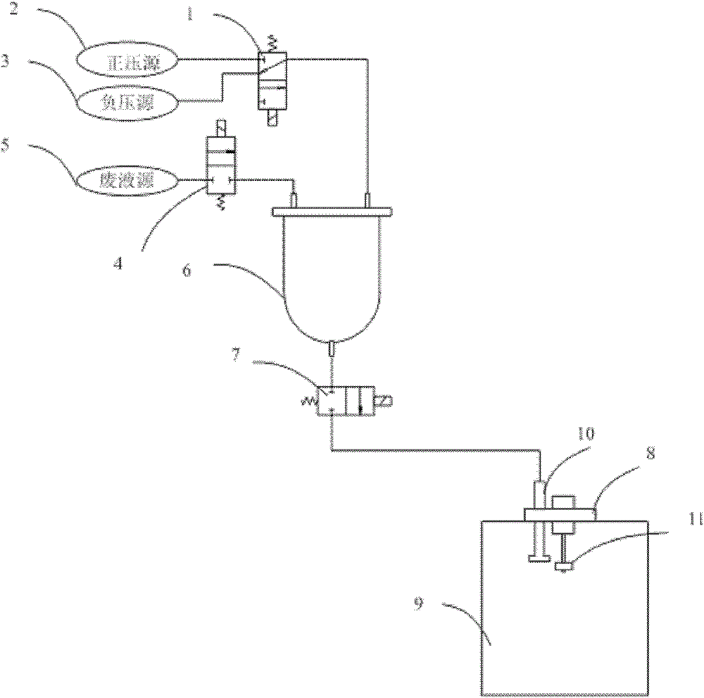
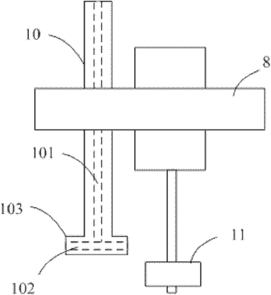
[0024] Please refer to figure 1 In the shown embodiment, the waste liquid discharge system includes: a pressure switching valve 1, a positive pressure source 2, a negative pressure source 3, a waste liquid source valve 4, a waste liquid source 5, a liquid storage tank 6, a waste liquid discharge valve 7 and a waste liquid A liquid collection device, the waste liquid collection device comprises a container 9, a waste liquid discharge joint 10 and a liquid level detection device 11, and the waste liquid discharge joint 10 and the liquid level detection device 11 are all arranged on the top of the container 9, such as the top or side of the container 9 upper edge of the wall. One end of the waste liquid discharge joint 10 communicates with the waste liquid discharge valve 7 , and the other end extends into the container 9 for discharging the waste liquid into the container 9 . The liquid level detection device 11 is used to detect the liquid level, and when the liquid level reac...

Embodiment 2

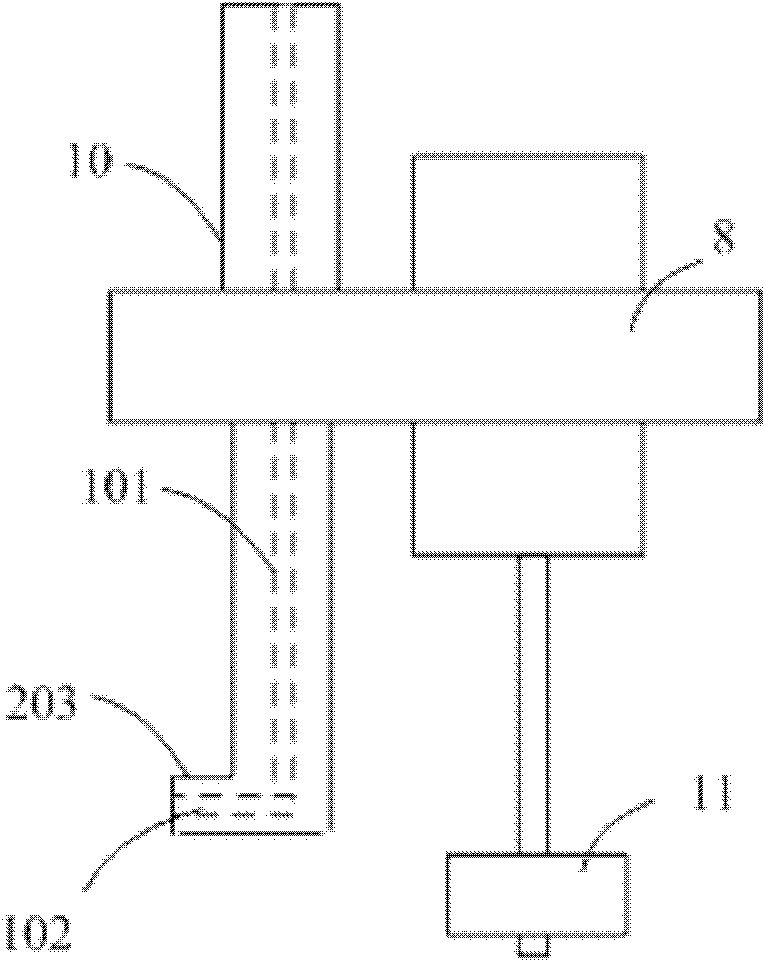
[0036] in such as image 3 In the shown embodiment, the waste liquid discharge joint 10 is different from the above-mentioned embodiments. In this embodiment, the shape of the waste liquid discharge joint 10 is "L" shape, that is, the bottom of the waste liquid discharge joint has a An outwardly extending arm 203, said arm 203 is arranged horizontally or substantially horizontally. A diversion hole 101 and a diversion hole 102 are opened inside the waste liquid discharge joint 10, the diversion hole 101 communicates with the diversion hole 102, the diversion hole 102 is opened in the arm 203, and the diversion hole 102 is also arranged horizontally or substantially horizontally . In this case, the discharge direction of the waste liquid is horizontal, and the flow of the waste liquid impinges on the inner side wall of the container.

Embodiment 3

[0038] in such as Figure 4 In the shown embodiment, the shape of the waste liquid discharge joint 10 is an approximate "L" shape, that is, the bottom of the waste liquid discharge joint has an arm 303 extending outward from the side wall, and the arm 303 is at a certain angle to the horizontal direction. An included angle, the included angle may be an angle greater than 0° and less than 60°, such as 30° or 50°. The direction changing hole 102 is opened in the arm 303, and the angle between the axis direction of the direction changing hole 102 and the horizontal line is also in the range of 0° to 60°, such as 30° or 50°. In this case, the discharge direction of the waste liquid is obliquely upward.


PUM


Abstract

The invention discloses a waste liquid collection device, a waste liquid discharge system and a discharge method. The waste liquid collection device includes a container for containing liquid; a liquid level detection device arranged on the upper part of the container; A discharge joint, the waste liquid discharge joint includes a diversion hole and a diversion hole, the diversion hole is set on the liquid inlet side of the waste liquid discharge joint, and the change direction hole is set on the liquid outlet side of the waste liquid discharge joint, The diversion hole communicates with the diversion hole, and is used to discharge the liquid into the container from the outside, and the diversion hole is configured to allow the liquid to impact on the side wall of the container after being discharged from the waste liquid discharge joint . The discharge direction of the waste liquid is changed through the direction-changing hole, so that the waste liquid directly impacts on the side wall of the container, avoiding the waste liquid directly impacting the waste liquid surface and generating foam, thereby improving the accuracy of liquid level detection.

Description

technical field [0001] The invention relates to a medical device, in particular to a medical waste liquid collection device, a waste liquid discharge system and a discharge method. Background technique [0002] General body fluid testing instruments will use various reagents, and the reagents need to be discharged out of the machine after use. Generally, there are two ways to discharge the waste liquid: one is to directly use the liquid pump to extract the waste liquid out of the machine. If it flows through the liquid pump, it is easy to damage the liquid pump and affect its life; the second is to use a liquid storage tank with pressure switching to collect and discharge waste liquid, and the pressure source is generally a large flow air pump. First switch the liquid storage tank to negative pressure, which is used to collect the waste liquid of each channel. After collecting to a certain extent, switch the liquid storage tank to positive pressure, and discharge the waste...

Claims


Application Information

Patent Timeline
Patent Type & Authority Patents(China)
IPC IPC(8): A61G12/00
Inventor 谢子贤
Owner SHENZHEN MINDRAY BIO MEDICAL ELECTRONICS CO LTD
Why Eureka
Try Eureka