Magnetic conductive block, electromagnetic suction platform having same and milling machine
A technology of electromagnetic attraction and magnetic block, which is applied in the direction of milling machine equipment, milling machine equipment details, clamping, etc., can solve the problems of high tool cost, low workpiece processing quality, and low efficiency, so as to improve processing efficiency and increase clamping force and prolong tool life
- Summary
- Abstract
- Description
- Claims
- Application Information
AI Technical Summary
Problems solved by technology
Method used
Image
Examples
Embodiment 1
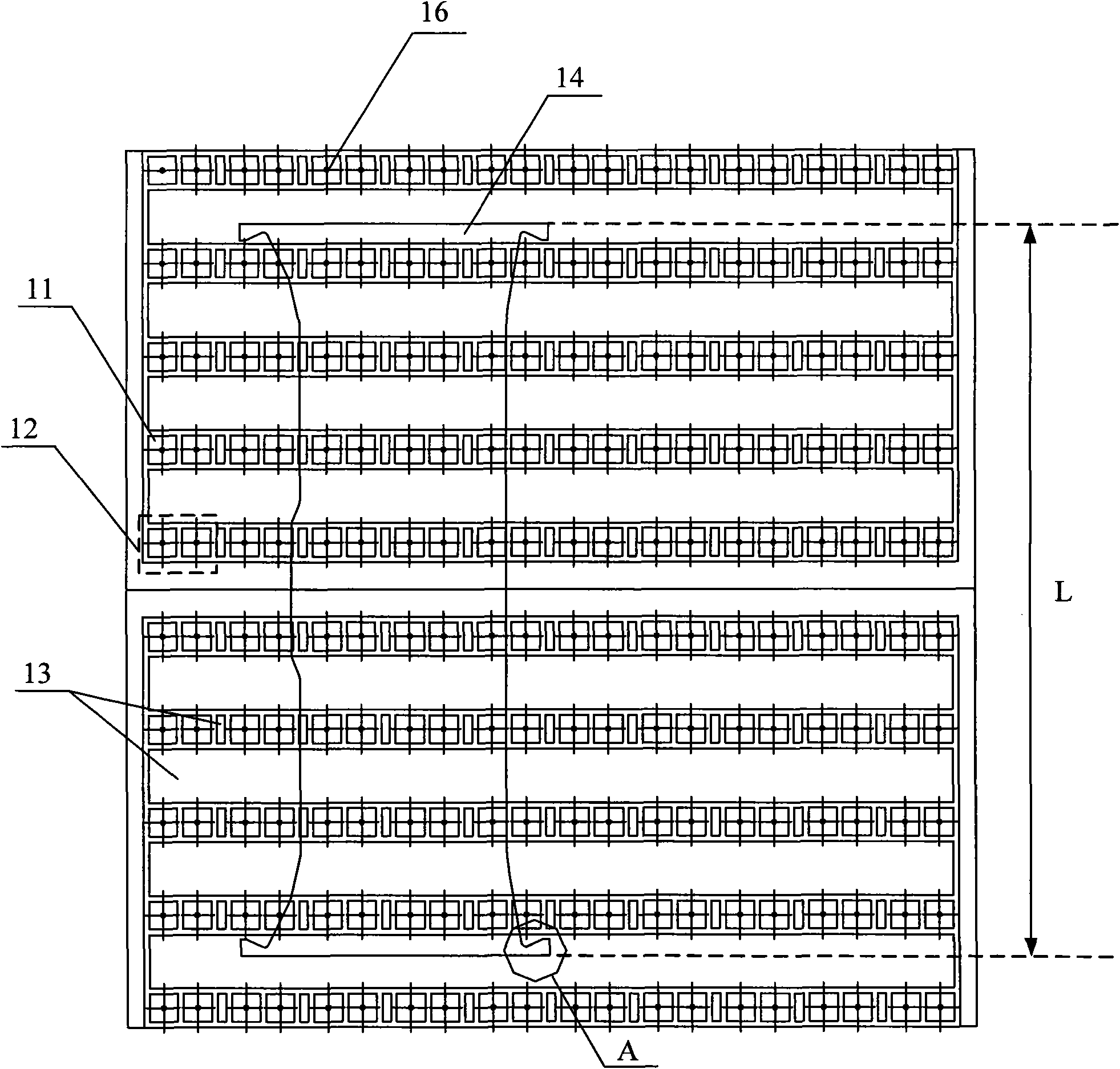
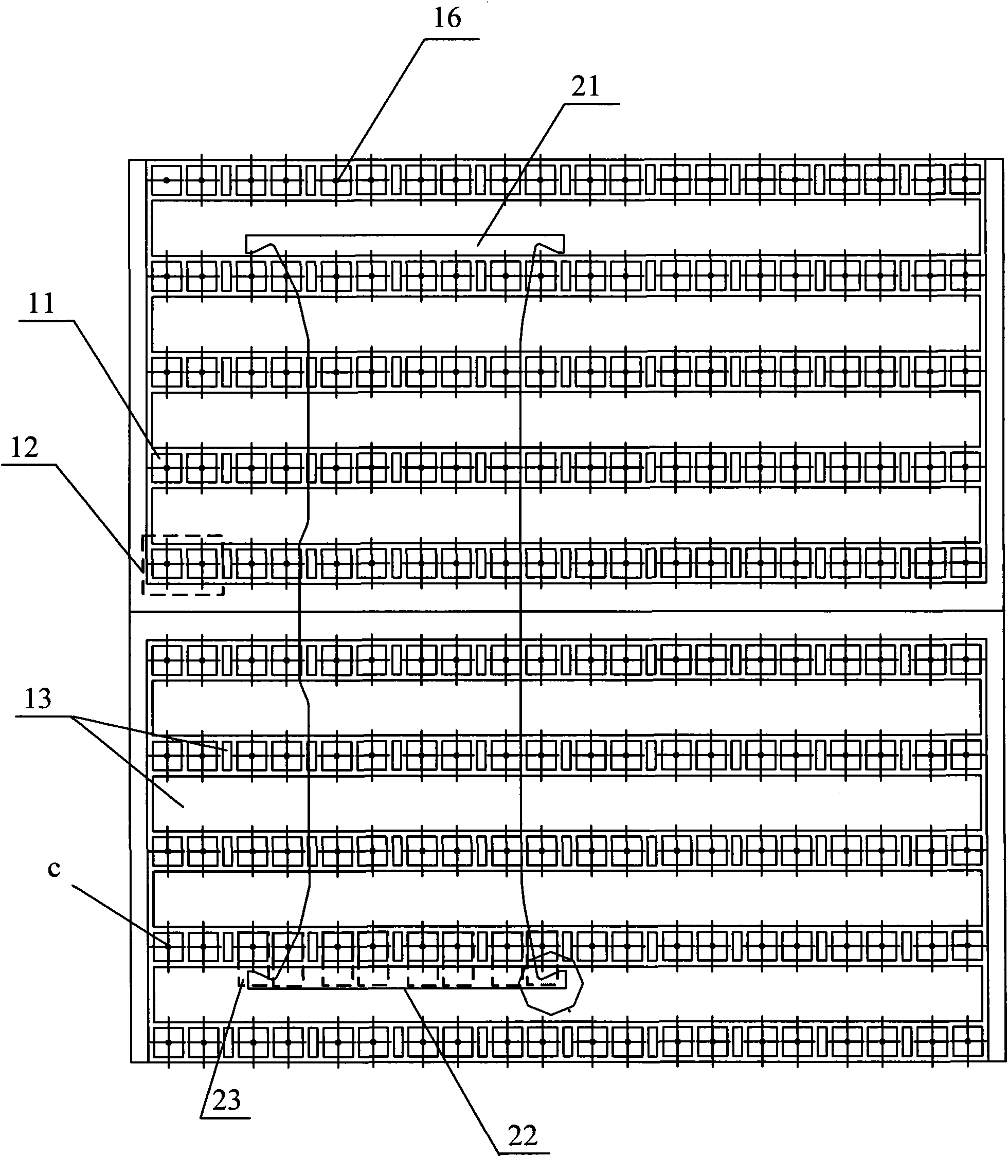
[0040] image 3 It is a schematic diagram of the application structure of Embodiment 1 of the magnetic permeable block of the present invention. This embodiment takes the ST50 electromagnetic suction platform of Qiaofu VIA6023 CNC gantry milling machine as an example, and uses this platform to process "I"-shaped workpieces. For example, the "I"-shaped workpieces can be Cover the locomotive frame. Those skilled in the art can understand that workpieces of other shapes can also be processed, as long as the problem solved by the present invention is similar, they can all be applicable to the solution of this embodiment.
[0041] like image 3 As shown, the electromagnetic attraction platform of this embodiment is provided with multiple columns of magnetic poles 11 , and a demagnetization zone 13 is provided between every two adjacent columns and between every two pairs of magnetic poles 12 . Above the magnetic pole 11 , a magnetically permeable block is connected to the magneti...
Embodiment 2
[0051] Image 6 It is a schematic diagram of the application structure of Embodiment 2 of the magnetic permeable block of the present invention, such as Image 6 As shown, the width of the workpiece 31 in this embodiment is slightly larger than the width of the first embodiment, and the distance beyond the magnetic pole row c is slightly farther, but it still does not reach the next magnetic pole row d, and is also in a suspended state.
[0052] In this embodiment, the second magnetically conductive block 32 is also provided to support the workpiece 31 and improve the adsorption force. The structure of the second magnetic block 32 can be referred to Figure 7 and Figure 8 , Figure 7 It is the front view of Embodiment 2 of the magnetic permeable block of the present invention, Figure 8 It is a top view of Embodiment 2 of the magnetic permeable block of the present invention. The second magnetic block 32 is basically a cuboid, which may include a first surface 33 and a s...
Embodiment 3
[0057] The embodiment of the present invention also provides an electromagnetic attraction platform, where more than one row of magnetic poles are distributed on the electromagnetic attraction platform, and magnetic conductive blocks are arranged on the magnetic poles. Wherein, at least the magnetically permeable block provided on the magnetic pole for supporting the edge of the workpiece is the magnetically permeable block described in any embodiment of the present invention. In a specific implementation, the magnetic permeable block described in any embodiment of the present invention can be provided only at the magnetic pole for supporting the edge of the workpiece, and the magnetic permeable block can also be further provided at other positions of the electromagnetic attraction platform, as long as it can be solved The problem of insufficient support of the workpiece can only increase the clamping force on the workpiece, prolong the life of the tool, and improve the process...
PUM
| Property | Measurement | Unit |
|---|---|---|
| Height | aaaaa | aaaaa |
Abstract
Description
Claims
Application Information
 - R&D
- Intellectual Property
- Life Sciences
- Materials
- Tech Scout
- Unparalleled Data Quality
- Higher Quality Content
- 60% Fewer Hallucinations
Browse by: Latest US Patents, China's latest patents, Technical Efficacy Thesaurus, Application Domain, Technology Topic, Popular Technical Reports.
© 2025 PatSnap. All rights reserved.Legal|Privacy policy|Modern Slavery Act Transparency Statement|Sitemap|About US| Contact US: help@patsnap.com


