Thermal waste water treatment apparatus and method employing heat pump

A technology for waste water treatment and heat pump, applied in the direction of degassed water/sewage treatment, etc., can solve the problem of non-standard discharge, and achieve the effect of reducing energy consumption, low energy consumption and simple installation

Active Publication Date: 2013-06-05
SHANGHAI HANZHUO ENERGY TECH
View PDF5 Cites 2 Cited by
  • Summary
  • Abstract
  • Description
  • Claims
  • Application Information

AI Technical Summary

Problems solved by technology

[0013] The disadvantage of this scheme is that it cannot discharge up to the standard, and the sludge needs deep treatment

Method used


Image

  • Thermal waste water treatment apparatus and method employing heat pump

Examples


Embodiment Construction

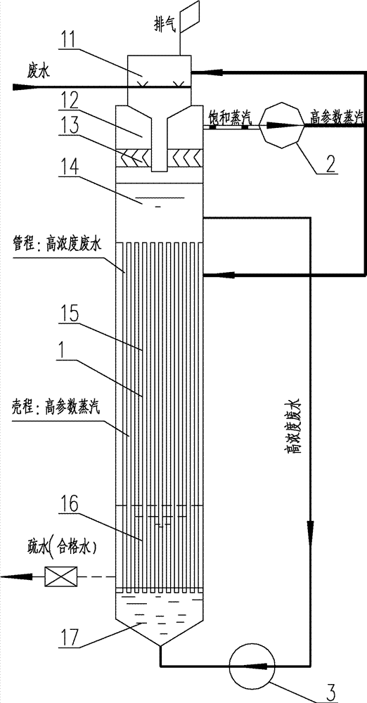
[0034] Such as figure 1 As shown, a thermal wastewater treatment device using a heat pump in the present invention includes: a wastewater evaporator 1 , a heat pump 2 and a wastewater circulation pump 3 . From top to bottom, the wastewater evaporator consists of a wastewater deaeration zone 11, a saturated steam zone 12, a demister 13, a high-concentration wastewater retention zone 14, a heat exchange zone 15, a hydrophobic storage zone 16 and a high-concentration wastewater distribution zone 17.

[0035] The heat pump 2 is used to increase the steam parameter of the saturated steam from the saturated steam zone 12, and transmit the high-parameter steam to the heat exchange zone 15 and the wastewater deaeration zone 11.

[0036] The wastewater circulating pump 3 is used to transfer the high-concentration wastewater from the high-concentration wastewater retention area 14 to the high-concentration wastewater distribution area 17 .

[0037] The waste water deoxygenation zone 11...


PUM


Abstract

The invention discloses a thermal waste water treatment apparatus employing a heat pump. The apparatus comprises a waste water evaporator, a heat pump and a waste water circulating pump; and the waste water evaporator comprises a waste water deoxidizing zone, a saturated vapor zone, a demister, a high concentration waste water stagnation zone, a heat exchange zone, a drain storage zone and a highconcentration waste water distribution zone from top to bottom. In addition, the invention also discloses a thermal waste water treatment method employing the heat pump. Waste water is first evaporated into water vapor; the heat pump is used to increase steam parameters, and the steam is supplied to the heat exchange zone and cools the high concentration waste water into qualified condensed water, which is drained outside; the high concentration waste water absorbs vaporization latent heat of the steam with high parameters, then part of the high concentration waste water evaporates into watervapor; so a heat circulation is completed. According to the invention heat is only needed during a starting process; at other time, the heat circulation within the apparatus is utilized to reduce energy consumption of the apparatus. The apparatus of the invention is simple, has small land occupation, low costs; and the quality of condensed water at a waste water outlet level reaches national highstandard.

Description

technical field [0001] The invention relates to a wastewater treatment device, in particular to a thermal wastewater treatment device using a heat pump; in addition, the invention also relates to a thermal wastewater treatment process using a heat pump. Background technique [0002] In industrial systems, such as limestone-gypsum wet flue gas desulfurization process, desulfurization will produce a certain amount of wastewater, which contains a certain amount of solids, chloride ions, sulfate ions and a small amount of heavy metals. [0003] At present, the FGD (flue gas desulfurization) wastewater system of a power plant usually adopts the following scheme: [0004] Option One: [0005] Wastewater is sent to the neutralization, sedimentation and flocculation triple tank of the wastewater treatment system, and then enters the clarifier and outlet tank arranged indoors, and the outlet water level is arranged in steps to form a gravity flow. [0006] The sludge dewatering equ...

Claims


Application Information

Patent Timeline
Patent Type & Authority Patents(China)
IPC IPC(8): C02F1/20
Inventor 刘上光
Owner SHANGHAI HANZHUO ENERGY TECH
Why Eureka
Try Eureka