Al technical title is built by PatSnap Al team. It summarizes the technical point description of the patent document.
A plugging machine and wire rope technology, which is applied in the field of rope plugging machines, can solve the problems of unsightly, difficult, and labor-intensive manual plugging, and achieve the effects of smooth plugging parts, simple operation, and simple production
Inactive Publication Date: 2012-03-14
枣庄矿业集团高庄煤业有限公司
View PDF9 Cites 2 Cited by
Summary
Abstract
Description
Claims
Application Information
AI Technical Summary
This helps you quickly interpret patents by identifying the three key elements:
Problems solved by technology
Method used
Benefits of technology
Problems solved by technology
Manual insertion is labor-intensive, laborious and difficult
Use rope clips to damage the main rope, which is not beautiful, and the extra cost is invested
Method used
Image
Click on the blue label to locate the original text in one second.
Reading with bidirectional positioning of images and text.
Examples
Embodiment Construction
[0018] The present invention will be further described below in conjunction with accompanying drawing and specific embodiment:
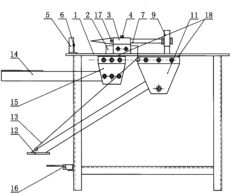
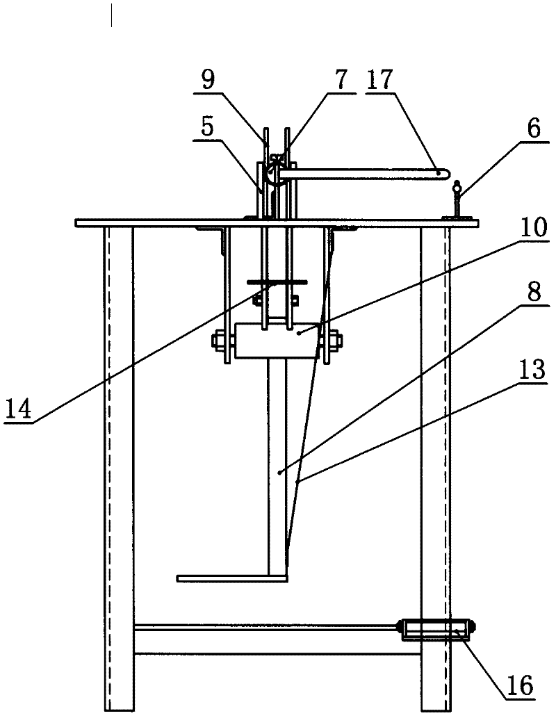
[0019] The structure of the present invention is as figure 1 , 2 As shown, a wire rope insertion machine includes a workbench 1, a rope retaining vertical plate 5, a flat cone 7, and a shaft bracket 11, and is characterized in that: the cone bracket 2 is fixedly installed on the workbench 1, and the shaft sleeve 3 Connected on the pointed cone support 2 by bolts, the pointed end of the flat pointed cone 7 is sleeved in the shaft sleeve 3, the rod system shift fork 9 is stuck in the groove at the end of the flat pointed cone 7, and the rope retaining vertical plate 5 is installed on the On the workbench 1, the rope retaining vertical plate 5 and the flat pointed cone 7 are on the same straight line, the tail end of the rod system shift fork 9 is fixedly connected to the fulcrum shaft 10, and the tail end of the pedal 12 is fixedly connected to the fu...
PUM
Abstract
The invention discloses a steel wire rope splicing machine, which comprises a work table, a rope blocking vertical plate, a flat sharp cone and a rotating shaft support frame, wherein a sharp cone support frame is fixedly arranged on the work table, a shaft sleeve is connected onto the sharp cone support frame through a screw bolt, a sharp head of the flat sharp cone is sheathed into the shaft sleeve, a rod system pulling fork is clamped in a groove arranged at the tail end of the flat sharp cone, the rope blocking vertical plate is arranged on the work table and is positioned on the same straight line with the flat sharp cone, the tail end of the rod system pulling fork is fixedly connected onto a fulcrum rotating shaft, the tail end of a pedal is fixedly connected onto the fulcrum rotating shaft, the fulcrum rotating shaft is connected onto the rotating shaft support frame through a shaft, the two support frames are welded at the bottom surface of the work table, and the rotating support frame is arranged on one support frame through screw bolts. The steel wire rope splicing machine has the advantages that the labor is saved, high speed, convenience and safety are realized, and the efficiency is high. A rope core of a spliced steel wire rope is not damaged, the splicing position is flat and smooth, the appearance is attractive, the splicing requirement is met, the regulation standard is reached, the manufacture is simple, the cost is low, and the operation is simple.
Description
technical field [0001] The invention relates to a rope insertion machine for inserting a rope into a steel wire rope, in particular to a wire rope insertion machine. Background technique [0002] Wire rope is an indispensable means of production in the entire national industrial and agricultural production, and its role is irreplaceable by other materials. Wire rope splicing is very common and commonly used in production, and it is also a very important link. The labor intensity of manpower plugging is big, laborious, difficult. Using rope clamps to damage the main rope is unsightly and requires unnecessary investment. Contents of the invention [0003] The object of the present invention is to provide a wire rope splicing machine which is convenient, quick, easy to operate and saves manpower. [0004] To achieve the above object, the technical solution adopted in the present invention is: [0005] A wire rope insertion machine, including a workbench, a rope retaining ...
Claims
Application Information
Patent Timeline
Application Date:The date an application was filed.
Publication Date:The date a patent or application was officially published.
First Publication Date:The earliest publication date of a patent with the same application number.
Issue Date:Publication date of the patent grant document.
PCT Entry Date:The Entry date of PCT National Phase.
Estimated Expiry Date:The statutory expiry date of a patent right according to the Patent Law, and it is the longest term of protection that the patent right can achieve without the termination of the patent right due to other reasons(Term extension factor has been taken into account ).
Invalid Date:Actual expiry date is based on effective date or publication date of legal transaction data of invalid patent.