Valve core of butterfly valve

A spool and butterfly valve technology, applied in the field of butterfly valve spools, can solve problems such as bad effects of durability, increase of bad effects, and poor productivity, and achieve the effects of ensuring strength, improving flow characteristics, and reducing weight

Active Publication Date: 2015-07-22
KITZ CORP
View PDF4 Cites 0 Cited by
  • Summary
  • Abstract
  • Description
  • Claims
  • Application Information

AI Technical Summary

Problems solved by technology

When the valve core is strained, plastic deformation occurs, and the sealing performance decreases, which adversely affects durability.
The spool is generally manufactured by casting in many cases. Especially, if the spool with a middle diameter or more is provided with ribs by casting, the difference in wall thickness between the thick-walled part and the thin-walled part of the spool will increase, and casting will easily occur. Bad, as the valve diameter increases, the adverse effects of the wall thickness difference also increase
On the other hand, although it is also possible to manufacture a valve core with ribs by welding, in this case, productivity deteriorates and cost increases, so it is not a general case.

Method used


Image

  • Valve core of butterfly valve
  • Valve core of butterfly valve
  • Valve core of butterfly valve

Examples


Embodiment Construction

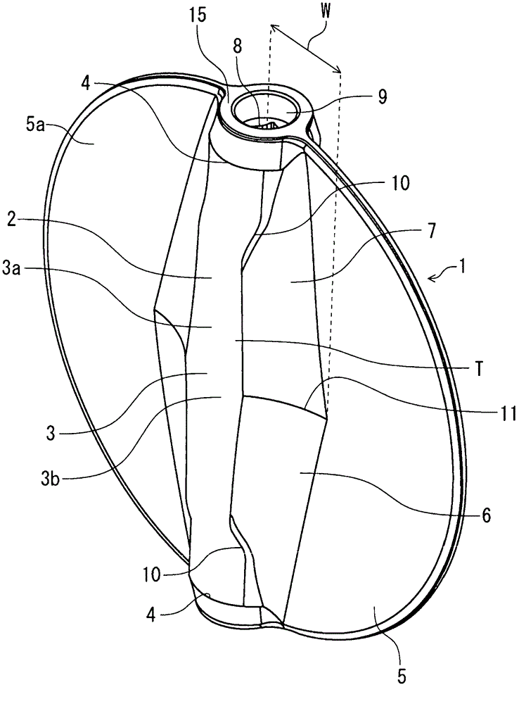
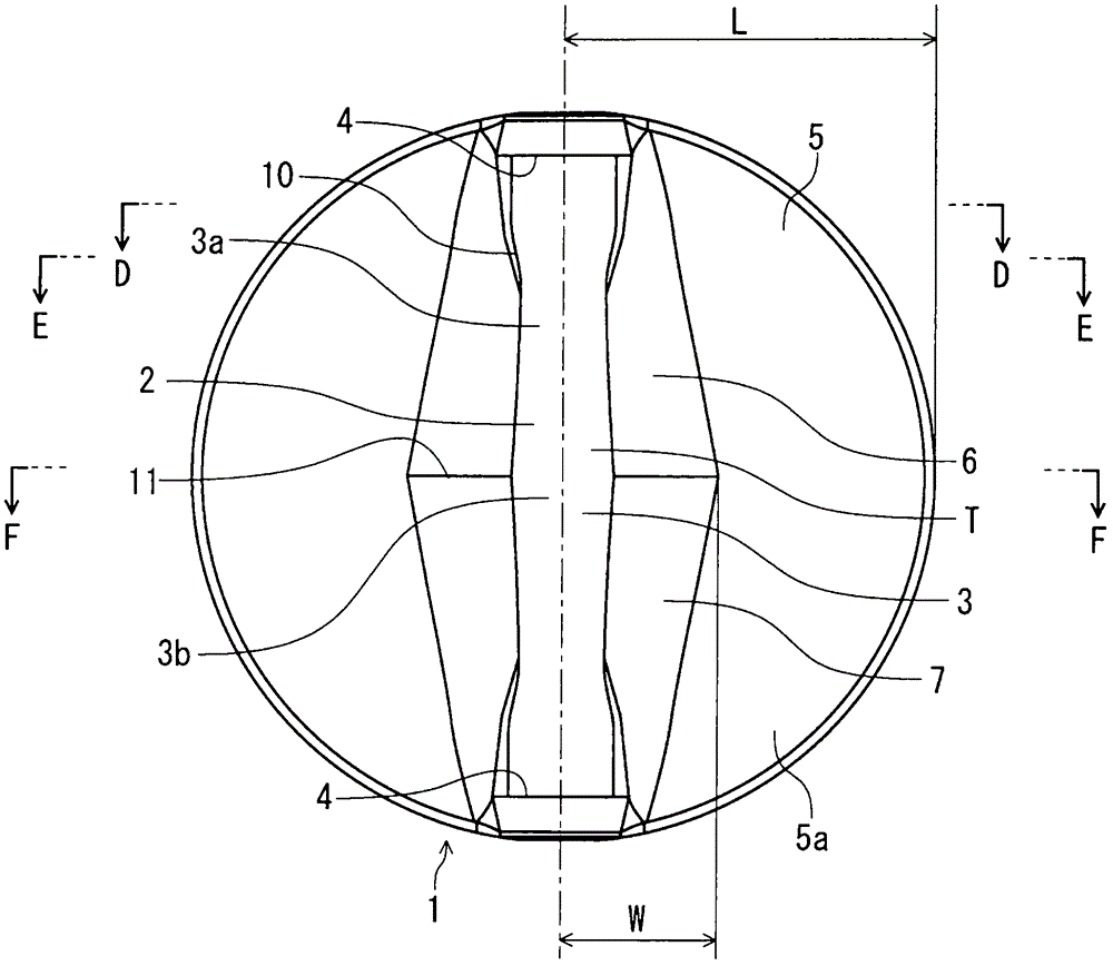
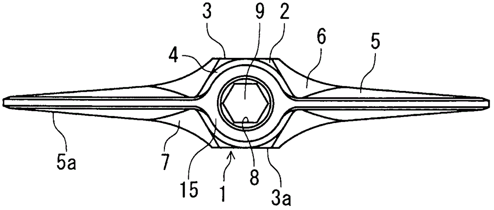
[0037] Hereinafter, preferred embodiments of the valve core of the butterfly valve in the present invention will be described in detail with reference to the drawings. figure 1 In, the perspective view of the spool of the butterfly valve in the present invention is shown, figure 2 in, means figure 1 top view of image 3 in, means figure 2 top view. Image 6 , shows a more detailed perspective view of the valve element of the butterfly valve of the present invention.

[0038] As shown in the figure, the valve core 1 of the butterfly valve in the present invention is formed into a disc shape, and is in the shape of a boss part 2 arranged continuously in the longitudinal direction from the top to the bottom, and the boss part 2 forms a cylindrical cross-sectional hexagon Part 3, cross-sectional circular part 4, and the boss part 2 and the valve leaf part 5 of the valve core 1 are connected by a connecting R part 7 with a gradual change R6.

[0039] In the valve core 1 of t...


PUM


Abstract

PROBLEM TO BE SOLVED: To provide a valve body of a butterfly valve capable of enhancing strength by dispersing stress when the valve is closed while enhancing torque performance when operating the valve by reducing the weight of the whole body. SOLUTION: In the valve body of the butterfly valve in which the vertical boss 2 of disc-shape valve body 1 is continuously arranged in a longitudinal direction, the tubular hexagonal cross-sectional part 3 is formed in the center the area T of the boss 2 and the tubular circular cross-sectional parts 4 are formed near the stem fitting parts 8 at the top and the bottom other than the hexagonal cross-sectional part 3 in the valve body 1 of the butterfly valve. The boss 2 and the valve wing parts 5 are connected by the connection R parts 7 and the connection R parts 7 are connected by gradually changing part R6 set gradually from the small connection R to the large connection R from both top and bottom of the circular cross-sectional part 4 to the center 3b of the hexagonal cross-sectional part 3. COPYRIGHT: (C)2012,JPO&INPIT

Description

technical field [0001] The invention relates to a valve core of a butterfly valve, in particular to a valve core with a relatively large caliber, which requires strength against fluid pressure when the valve is closed. Background technique [0002] Generally, the valve core of the butterfly valve is rotatably assembled in the main body in a state where the valve core of the butterfly valve is rotatably installed in the main body embedded with the elastic seat ring in a state where the valve stem is supported in the radial direction. With this assembly structure, when the flow path of the butterfly valve is closed, a fluid pressure greater than that of the flow path is applied to the spool, especially due to the large diameter of about 350-600A, the nominal pressure is JIS 16K, 20K, In the case of ISO PN16, PN20, ASME class 125, and 150 or so, the area of ​​the spool subjected to fluid pressure also increases, so it is necessary to ensure the strength of the spool against the...

Claims


Application Information

Patent Timeline
Patent Type & Authority Patents(China)
IPC IPC(8): F16K1/36F16K1/48
Inventor 丸山泰秀吉田周平
Owner KITZ CORP
Why Eureka
Try Eureka