Heat exchanger and energy-saving shower

A heat exchanger and heat exchange plate technology, which is applied to indirect heat exchangers, heat exchanger types, heat exchanger shells, etc., can solve the problems of difficult processing, difficult to form, etc. Good effect of waste heat recovery

Inactive Publication Date: 2012-03-14
HAIER GRP CORP +1
View PDF8 Cites 2 Cited by
  • Summary
  • Abstract
  • Description
  • Claims
  • Application Information

AI Technical Summary

Problems solved by technology

[0003] The invention provides a heat exchanger and an energy-saving shower, which can solve the problems in the prior art that the heat exchange part of the main body of the heat exchanger adopts coil tubes or U-shaped flow channels, which are difficult to process and difficult to form.

Method used


Image

  • Heat exchanger and energy-saving shower
  • Heat exchanger and energy-saving shower
  • Heat exchanger and energy-saving shower

Examples


Embodiment 1

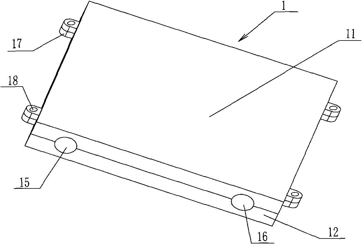
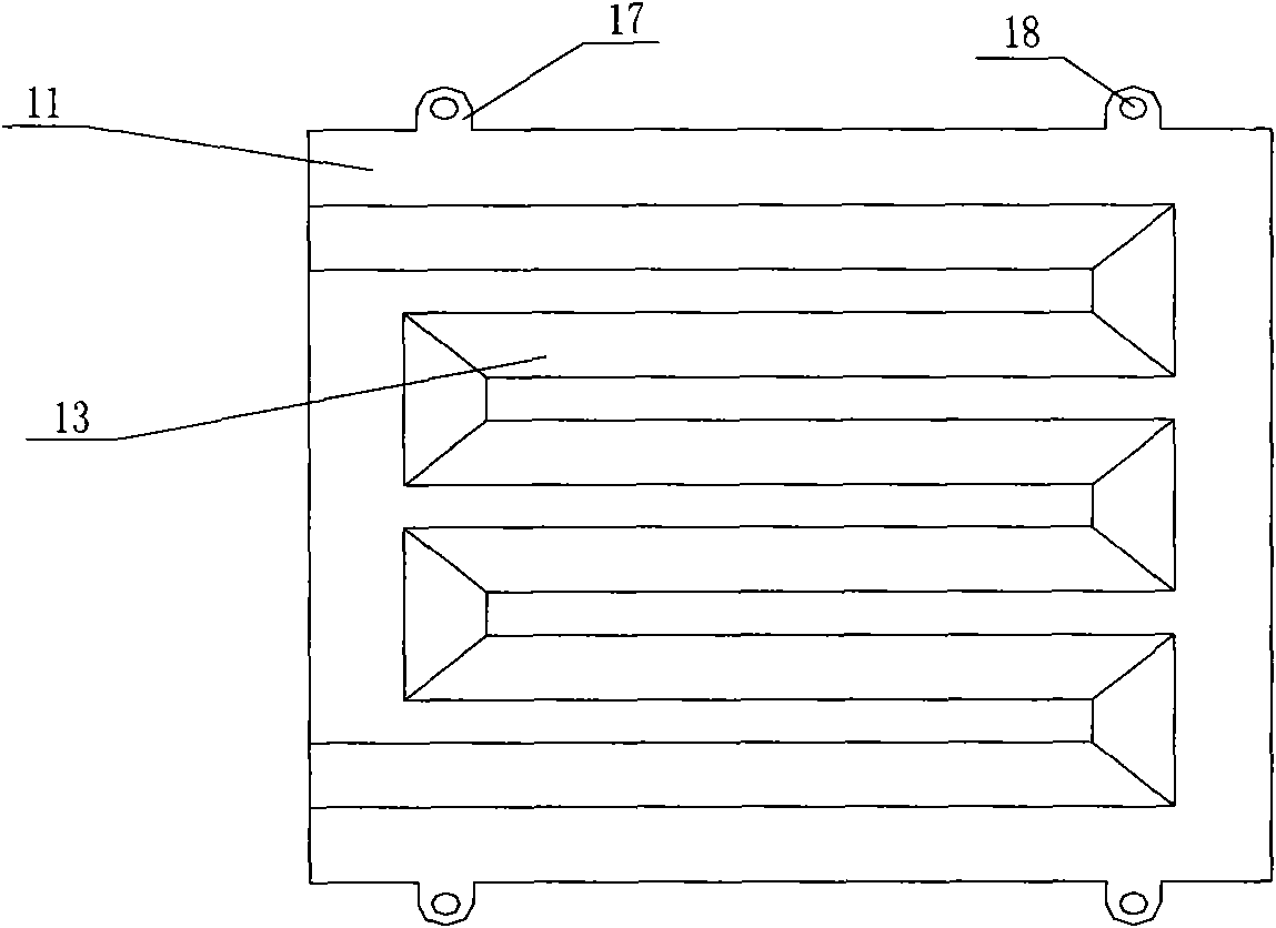
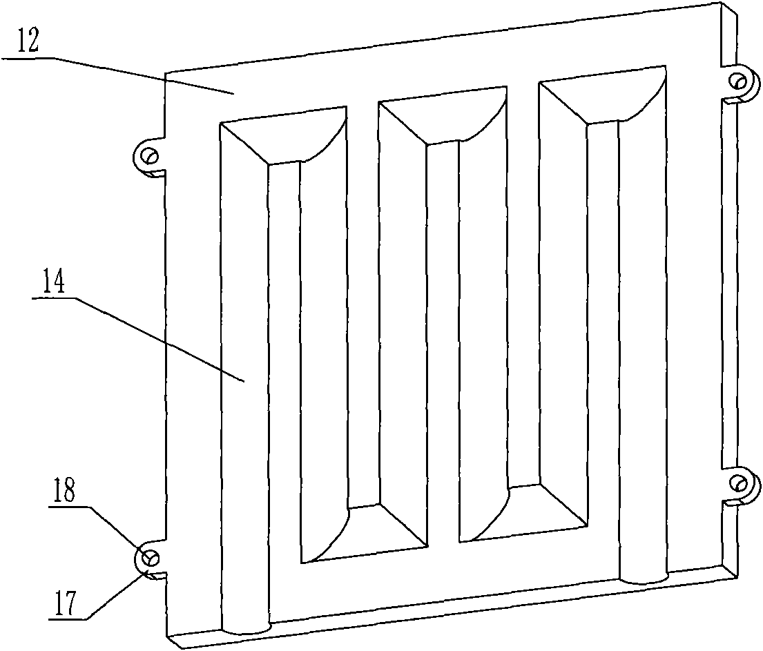
[0041] refer to Figure 1 to Figure 3 As shown, in order to separately process water flow channels or water flow grooves on the split structure of the main heat exchange part, the main heat exchange part in this embodiment is composed of an upper heat exchange plate 11 and a lower heat exchange plate 12, and the upper heat exchange plate 11 has a meandering upper water flow tank 13, the water inlet of the upper water flow tank 13 is located on one side of the upper heat exchange plate 11, the water outlet is located on the same side or the opposite side of the upper heat exchange plate 11, and the lower heat exchange plate 11 A lower water flow channel 14 is oppositely arranged on the plate 12, and the upper heat exchange plate 11 and the lower heat exchange plate 12 are sealed and tightly connected, so that the upper water flow channel 13 and the lower water flow channel 14 form a circuitous water flow channel.

[0042] Specifically, the upper heat exchange plate 11 and the l...

Embodiment 2

[0046] refer to Figure 4 to Figure 9 As shown, the difference from Embodiment 1 is that the heat exchange part of the main body in this embodiment includes a heat exchange plate 11', a head I12' and a head II13', and there are at least two water flow channels 14' inside the heat exchange plate 11' , the water flow channel 14' is a one-way linear channel, on the inner side of the head I12' and the head II13' (the orientation here is defined by the installation state of the head I12' and the head II13') There are at least two water flow grooves 15' respectively, adjacent water flow grooves 15' are communicated at intervals, the end of the heat exchange plate 11' is inserted into the water flow groove 15', and is sealed and fastened with the head I12' and the head II13' Connected so that the water flow channel 15' communicates with the water flow channel 14' to form a circuitous water flow channel, and the water inlet 16' and water outlet 17' of the water flow channel 15' are lo...

Embodiment 3

[0054] refer to Figures 10 to 14 As shown, the difference from the second embodiment is that the water flow grooves 15' are arranged at intervals at the ends of the adjacent water flow channels 14' in the heat exchange plate 11', and are used to communicate with the adjacent water flow channels 14' at intervals, and the heat exchange plate 11' The ends of the head are sealed and fastened with the head I12' and the head II13' respectively, and the water inlet 16' and the water outlet 17' of the water flow channel 14' are located on the head I12' or the head II13'. This embodiment is the same Taking a row of four unidirectional water flow channels 14' formed in the heat exchange plate 11' as an example, the water inlet 16' and the water outlet 17' are located on the head II 13'.

[0055] In this embodiment, the sealing and fastening methods of the heat exchange plate 11', the head I12' and the head II13' can refer to the records in the second embodiment, and the specific use pr...


PUM


Abstract

The invention provides a heat exchanger and an energy-saving shower. The heat exchanger comprises a main body heat exchanging part, wherein the main body heat exchanging part is in a split-type structure, and a circuitous water flow passage is formed inside the main body heat exchanging part. Water flow passages or water flow grooves are respectively processed on the branch parts of the main body heat exchanging part to be assembled into the circuitous water flow passage inside the main body heat exchanging part, so the flowing time of the water stream inside a pipeline can be increased, and the heat exchanger is convenient to process. In addition, all branch parts can be integrally molded, or the branch parts are connected with one another after partial branch parts are integrally molded, so the mass production can be facilitated, the service life is long, the reliability is high, and the surplus heat recycling efficiency is high.

Description

technical field [0001] The invention belongs to the field of bathroom equipment, and in particular relates to a heat exchanger and an energy-saving shower. Background technique [0002] People will produce a lot of waste water when bathing in their daily life. The temperature of the waste water is still high, and the heat in the water is a lot. If the heat of this part of waste water is recovered and utilized, it will be more energy-saving and environmentally friendly. Therefore, there are various heat exchangers that recycle the waste heat of bathing wastewater on the market to recover the waste heat of bathing wastewater. The heat exchanger is connected to the water flow circuit of the water heater and placed on the floor of the bathroom. People step on it when bathing. , the bathing wastewater falls directly on the heat exchanger, the most important part of which is the main heat exchange part, which is made of materials with good heat conduction, such as aluminum and cop...

Claims


Application Information

Patent Timeline
Patent Type & Authority Applications(China)
IPC IPC(8): F28D3/00F28F9/02F28F9/00
Inventor 王军马峰赵小勇孙强郑涛
Owner HAIER GRP CORP
Why Eureka
Try Eureka