
Camera module

A camera module and lens array technology, which is applied in installation, television, optics, etc., can solve the problems of increasing the total length of the optics and the thickness of portable electronic devices, and achieve the effect of small thickness and shortening the total length of the optics

Inactive Publication Date: 2012-03-14
HONG FU JIN PRECISION IND (SHENZHEN) CO LTD +1
View PDF3 Cites 88 Cited by
  • Summary
  • Abstract
  • Description
  • Claims
  • Application Information

AI Technical Summary

Problems solved by technology

In order to improve the resolution of the camera module, it is often necessary to add optical lenses, etc., resulting in an increase in the total optical length of the camera module (Optical Total Track Length), which in turn leads to an increase in the thickness of the portable electronic device
However, this is contrary to people's requirements for portable electronic devices to be thin, light and small.

Method used


Image

  • Camera module
  • Camera module
  • Camera module

Examples


Embodiment Construction

[0041] The technical solution will be further described in detail below in conjunction with the accompanying drawings and embodiments.

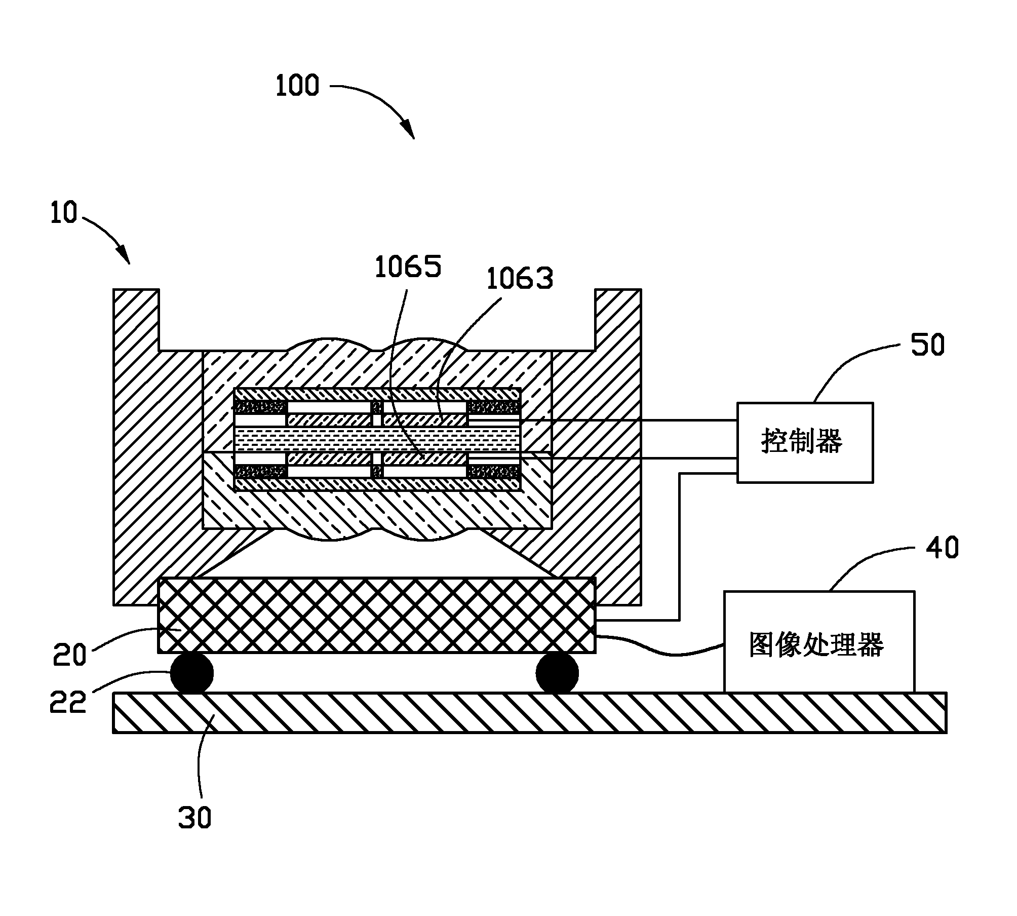
[0042] see figure 1 , a preferred embodiment of the present invention provides a camera module 100 . The camera module 100 includes a composite lens 10 , a controller 50 , an image sensor 20 , an image processor 40 and a circuit board 30 . The image sensor 20 is soldered on the circuit board 30 through solder balls 22 . The image processor 40 is provided on the circuit board 30 . The image sensor 20 is electrically connected to the controller 50 and the image processor 40 respectively.

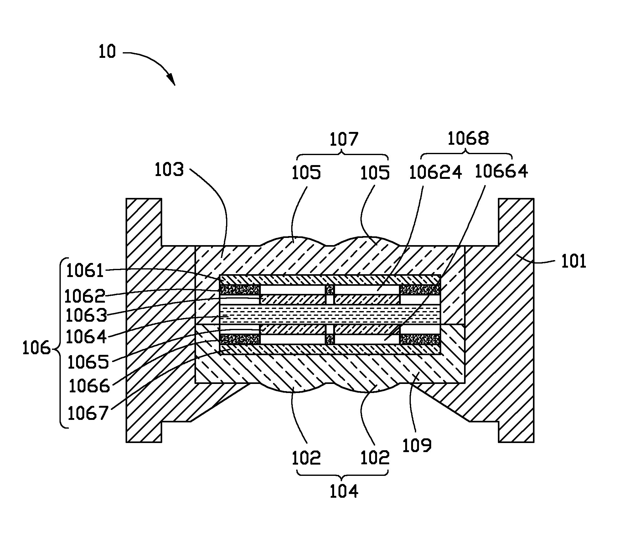
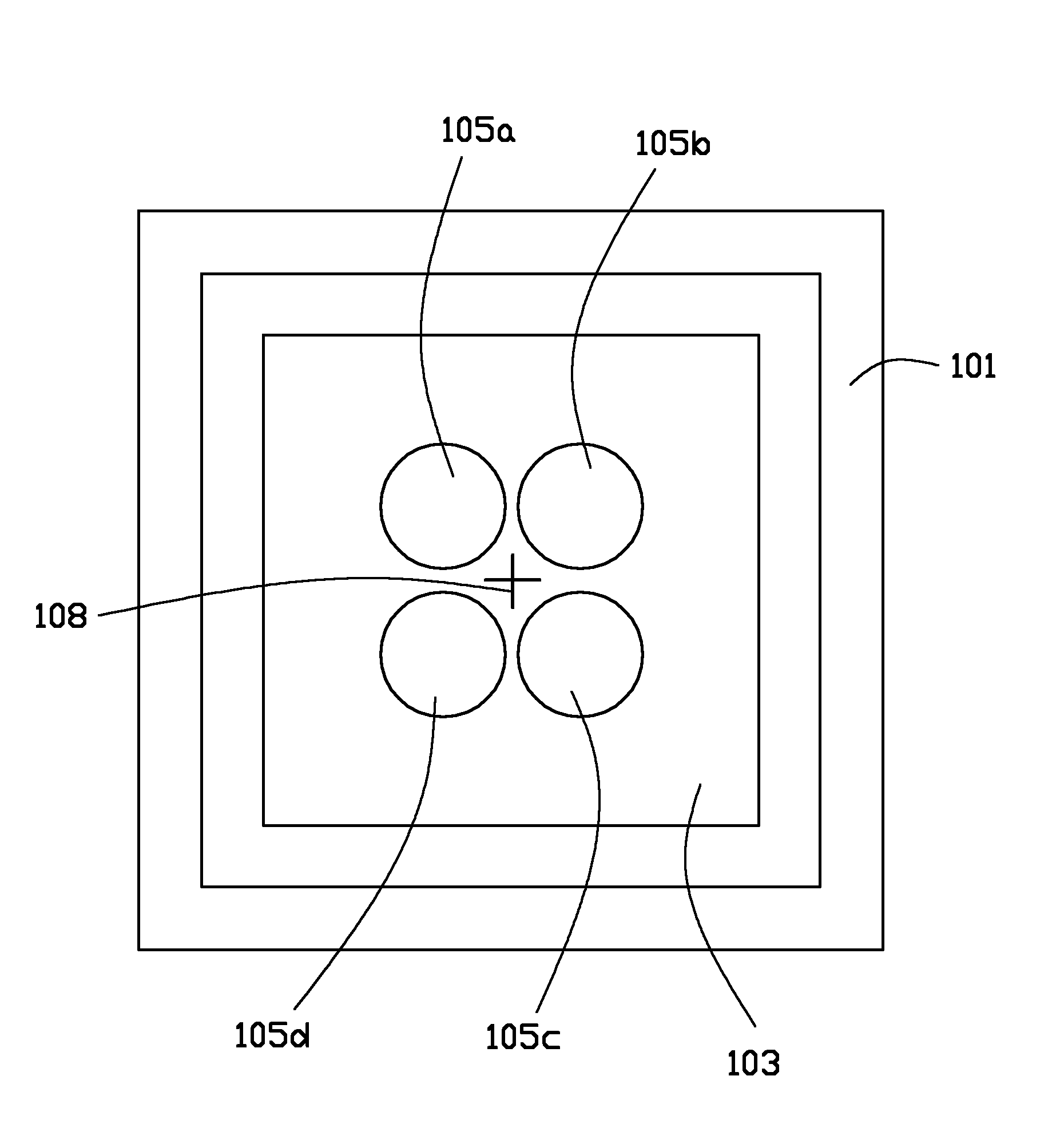
[0043] see figure 2 and image 3 , the composite lens 10 includes a mirror frame 101, an upper substrate 103, a lower substrate 109, a first lens array 107 formed on the upper substrate 103, a second lens array 104 formed on the lower substrate 109, and a lens array sandwiched between the upper substrate 103 and the lower substrate 109 between the liqu...


PUM


Abstract

The invention provides a camera module. The camera module comprises a first lens array, a second lens array, a liquid crystal shutter arranged between the first lens array and the second lens array, a controller, an image sensor and an image processor, wherein the first lens array comprises a plurality of first lens; the second lens array comprises a plurality of second lens which are respectively in optical alignment with the plurality of first lens one by one; the liquid crystal shutter is provided with a plurality of light-through holes; the plurality of transmission holes are respectively in optical alignment with the plurality of the first lens one by one; the controller is used for controlling every light-through hole of the liquid crystal shutter to open once in a shooting period; the image sensor is used for obtaining a sub-image corresponding to each light-through hole when each light-through hole in the shooting period is opened; and the image processor is used for synthesizing each sub-image corresponding to each light-through hole to an image by using a super-resolution image recovery technology.

Description

technical field [0001] The invention relates to a camera module. Background technique [0002] With the development of multimedia technology, people have higher and higher requirements for camera modules in portable electronic devices, for example, higher and higher resolution requirements. In order to improve the resolution of the camera module, it is often necessary to add optical lenses, etc., resulting in an increase in the total optical length (Optical Total Track Length) of the camera module, which in turn leads to an increase in the thickness of the portable electronic device. However, this is contrary to people's requirements for portable electronic devices to be thin, light and small. Contents of the invention [0003] In view of this, it is necessary to provide a camera module with high resolution and small thickness. [0004] A camera module includes a first lens array, a second lens array, a liquid crystal shutter arranged between the first lens array and the...

Claims


Application Information

Patent Timeline
IPC IPC(8): G02B7/02G02F1/1335G02F1/1333H04N5/225
Inventor 张仁淙
Owner HONG FU JIN PRECISION IND (SHENZHEN) CO LTD
Learn More