TFT-LCD (thin film transistor-liquid crystal display) driving circuit and liquid crystal display device

A technology for driving circuits and adjusting circuits, applied in static indicators, instruments, etc., can solve the problems of reducing charging time and affecting the aperture ratio of TFT-LCD, and achieve the effect of reducing the number, the aperture ratio has no adverse effect, and reducing the number of uses

Active Publication Date: 2012-03-14
BOE TECH GRP CO LTD +1
View PDF5 Cites 14 Cited by
  • Summary
  • Abstract
  • Description
  • Claims
  • Application Information

AI Technical Summary

Problems solved by technology

[0005] In the process of realizing the improvement scheme of the above-mentioned TFT-LCD, the inventor found that there are at least the following problems in the prior art: in the above-mentioned improvement scheme, although the number of source drivers is reduced, the production cost of the TFT-LCD can be reduced; but , by adding gate lines to respectively control the switching states of the pixels corresponding to the multiple data lines, the charging time of the pixel electrodes corresponding to the multiple data lines will be correspondingly reduced, and the additional gate lines will affect the TFT-LCD. opening ratio

Method used


Image

  • TFT-LCD (thin film transistor-liquid crystal display) driving circuit and liquid crystal display device
  • TFT-LCD (thin film transistor-liquid crystal display) driving circuit and liquid crystal display device
  • TFT-LCD (thin film transistor-liquid crystal display) driving circuit and liquid crystal display device

Examples


Embodiment 1

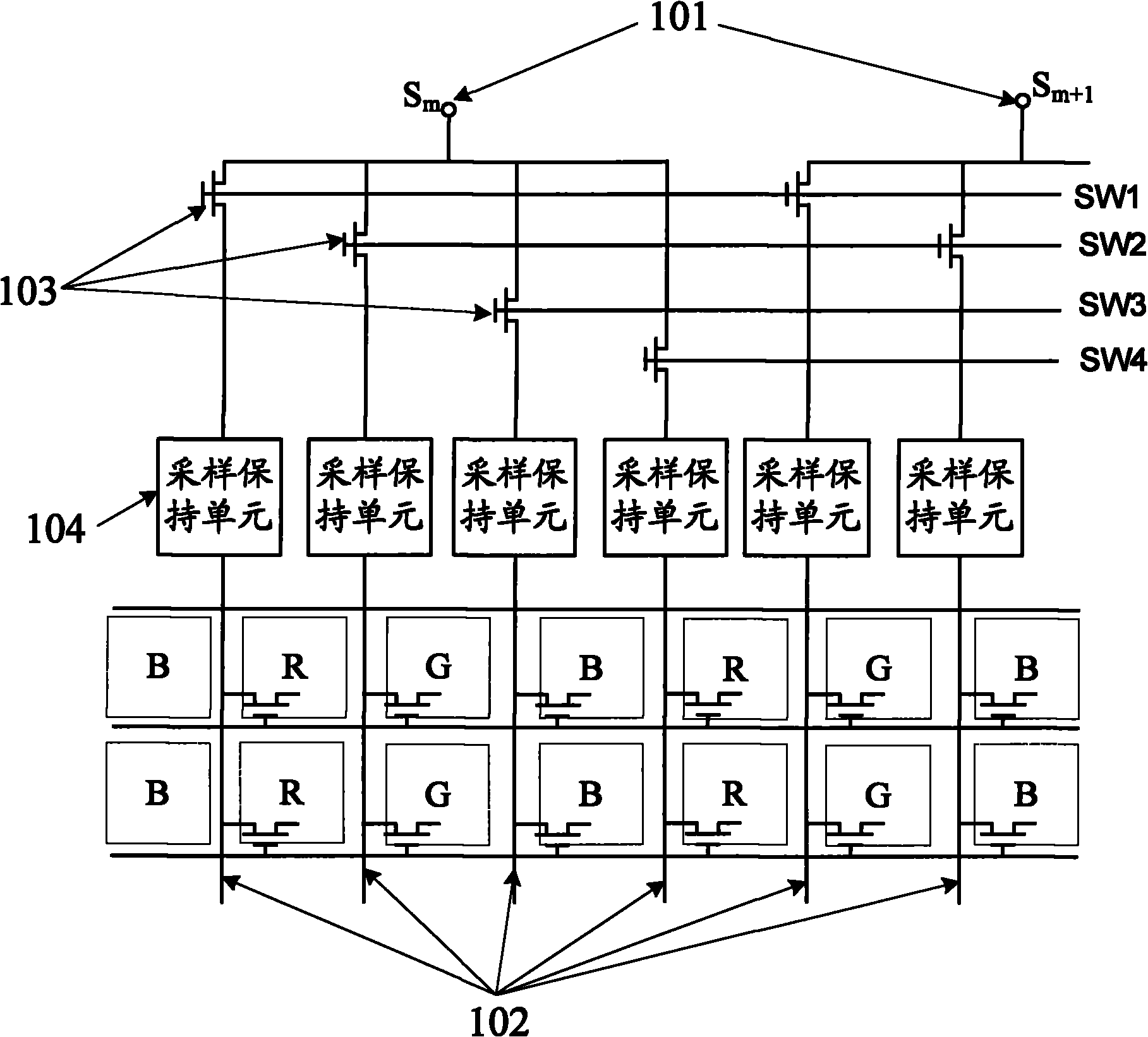
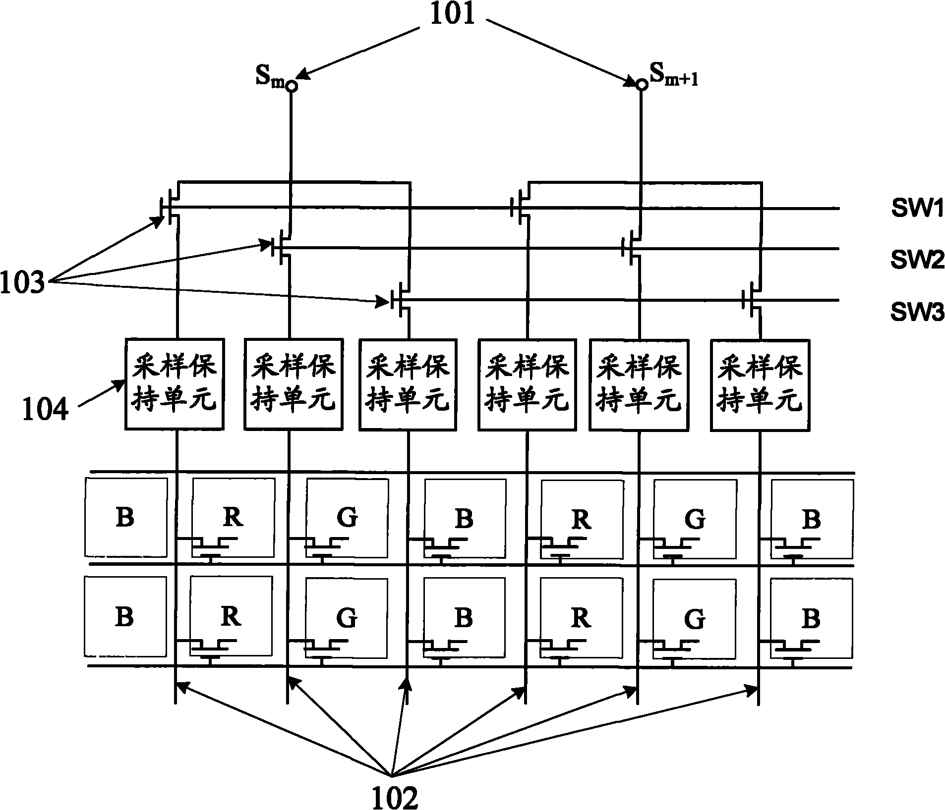
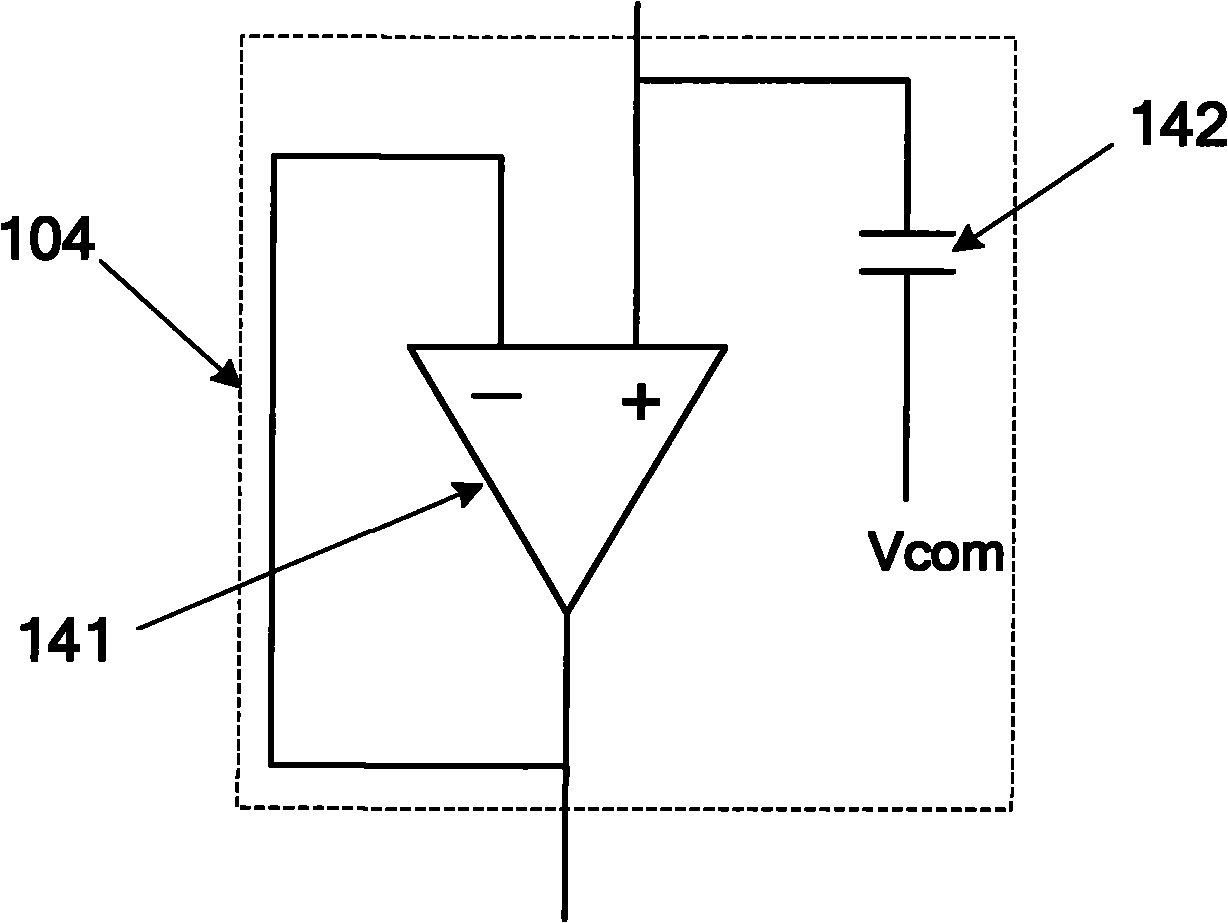
[0031] Such as figure 2 The TFT-LCD driver circuit shown, with figure 1 The basic principle of the TFT-LCD driving circuit described in is the same; however, in figure 2In the scheme, the output terminal 101 (Sm) of the source driver is connected to three data lines 102 at the same time, and the three data lines 102 correspond to red, green and blue sub-pixels of the same column of pixels respectively. Between the output terminal 101 of the source driver and the data line 102, a switch 103 and a sample and hold unit 104 are connected in series.

[0032] The same output terminal of a source driver is connected to 3 switching switches at the same time, and then connected to 3 sampling and holding units and 3 data lines; that is to say, the source driver can be controlled by the 3 switching switches. One of the output lines can time-divisionally provide 3 columns of sub-pixels with display data signals. Correspondingly, the number of sub-pixels whose data signals are provide...

Embodiment 2

[0049] In this example, for figure 2 The TFT-LCD driving circuit shown is further improved. Specific as Figure 5 shown.

[0050] The TFT-LCD driving circuit provided in this embodiment, in figure 2 On the basis of the TFT-LCD driving circuit shown, a data writing switch 105 is added; the data writing switch 105 is set between the sampling and holding unit 104 and the data line 102 .

[0051] The data writing switch 105 can be a MOS transistor; its gate is connected to the control terminal SW, and the signal of the control terminal SW can be provided by the timing controller of the TFT-LCD and amplified by the TFT-LCD driving circuit, and its source The electrode and the drain are connected to the sample and hold unit 104 and the data line 102 respectively.

[0052] In this way, when the control terminals SW1 and SW2 respectively control their corresponding switches to be turned on sequentially, the control terminal SW is always at a low level, and the data writing switc...

Embodiment 3

[0055] The principle of the TFT-LCD driving circuit provided in this embodiment is basically the same as that of the TFT-LCD driving circuits in Embodiment 1 and Embodiment 2.

[0056] However, in this embodiment, the TFT-LCD driving circuit further includes a timing controller (not shown in the figure) for controlling the switch 103; that is, the timing controller communicates with the The control terminals (SW1, SW2, SW3) of the switch 103 are connected to each other.

[0057] In this embodiment, the pulse heights provided by the timing controller for SW1, SW2, and SW3 are not exactly the same; The voltages are not exactly the same, and the turn-on voltages output to SW1, SW2, and SW3 after being amplified are also not exactly the same.

[0058] combine figure 2 or Figure 5 As shown, the turn-on voltages applied to the switching switches (MOS transistors) through SW1, SW2, and SW3 are different, that is, the voltages applied to the gates of the MOS transistors correspon...


PUM


Abstract

The embodiment of the invention discloses a TFT-LCD (thin film transistor-liquid crystal display) driving circuit and a liquid crystal display device, relating to the technical field of liquid crystal display and used for reducing the number of source drivers and reducing the manufacturing cost of a TFT-LCD under the condition of not affecting the normal charge of a pixel electrode. The TFT-LCD driving circuit comprises the source driver, and each output end of the source driver is connected with at least two data wires; furthermore, transfer switches of which the number corresponds to that of the data wires are arranged between the output ends of the source driver and the data wires, and the transfer switches are used for controlling the data transmission from the source driver to the data wires, wherein a sampling and holding unit is arranged between the transfer switches and the data wires, and the sampling and holding unit is used for saving display data which is provided from thesource driver to the data wires. The scheme provided in the embodiment of the invention is applicable to any thin-film transistor liquid crystal display equipment.

Description

technical field [0001] The invention relates to the technical field of liquid crystal display, in particular to a TFT-LCD drive circuit and a liquid crystal display device with the drive circuit. Background technique [0002] In a traditional TFT-LCD (Thin Film Transistor-Liquid Crystal Display, thin film transistor liquid crystal display), each data line (data line) is connected to an output line of a source driver (Source Driver); thus, in a In an internal liquid crystal display, the same number of source drivers as the number of data lines is required, resulting in higher cost of the source driver unit. [0003] In order to reduce the use of source drivers and reduce the production cost of TFT-LCD, the following improvement schemes exist in the prior art: [0004] A switch is set between the source driver and the data lines, so that the output line of one source driver is connected to multiple data lines at the same time through the switch, that is, the same source drive...

Claims


Application Information

Patent Timeline
Patent Type & Authority Applications(China)
IPC IPC(8): G09G3/36G09G3/20
Inventor 肖向春
Owner BOE TECH GRP CO LTD
Why Eureka
Try Eureka