Fully-automatic production line for high definition multimedia interface (HDMI) connector

A fully automatic, production line technology, applied in the direction of connection, line/collector parts, electrical components, etc., can solve the problems of low production efficiency, HDMI connector does not realize assembly line operation, etc., and achieve the effect of improving production efficiency

Inactive Publication Date: 2012-03-14
DONGGUAN LONGSHUN AUTOMATION TECH
5 Cites 35 Cited by

AI-Extracted Technical Summary

Problems solved by technology

[0003] The existing HDMI connector production equipment does not realize assembly line operation, the p...

Abstract

The invention discloses a fully-automatic production line for a high definition multimedia interface (HDMI) connector. The fully-automatic production line comprises a product molding part, a product detection part and a dustproof cover installation and product package part, wherein the product molding part comprises a terminal feed mechanism, a plastic body feed mechanism and an iron clad feed mechanism; the product detection part comprises a switch-on pressurization test mechanism, a charge coupled device (CCD) detection mechanism, a product connecting and conveying band, a first cylinder/conveying band unqualified product mechanism, a servo motor displacement mechanism and a second cylinder/conveying band unqualified product mechanism; and the dustproof cover installation and product package part comprises a dustproof cover cylinder displacement mechanism, a clamping jaw cylinder assembled dustproof cover, a second servo motor displacement mechanism, a second CCD detection mechanism and a third unqualified product screening mechanism and a package mechanism. The fully-automatic production line for the HDMI connector has the advantages of small occupied area, high continuity, high automation degree and high efficiency.

Application Domain

Line/current collector details

Technology Topic

Small footprintFully automatic +6

Image

  • Fully-automatic production line for high definition multimedia interface (HDMI) connector
  • Fully-automatic production line for high definition multimedia interface (HDMI) connector

Examples

  • Experimental program(1)

Example Embodiment

[0014] In order to facilitate the understanding of those skilled in the art, the structural principles of the present invention will be further described in detail below in conjunction with specific embodiments and accompanying drawings:
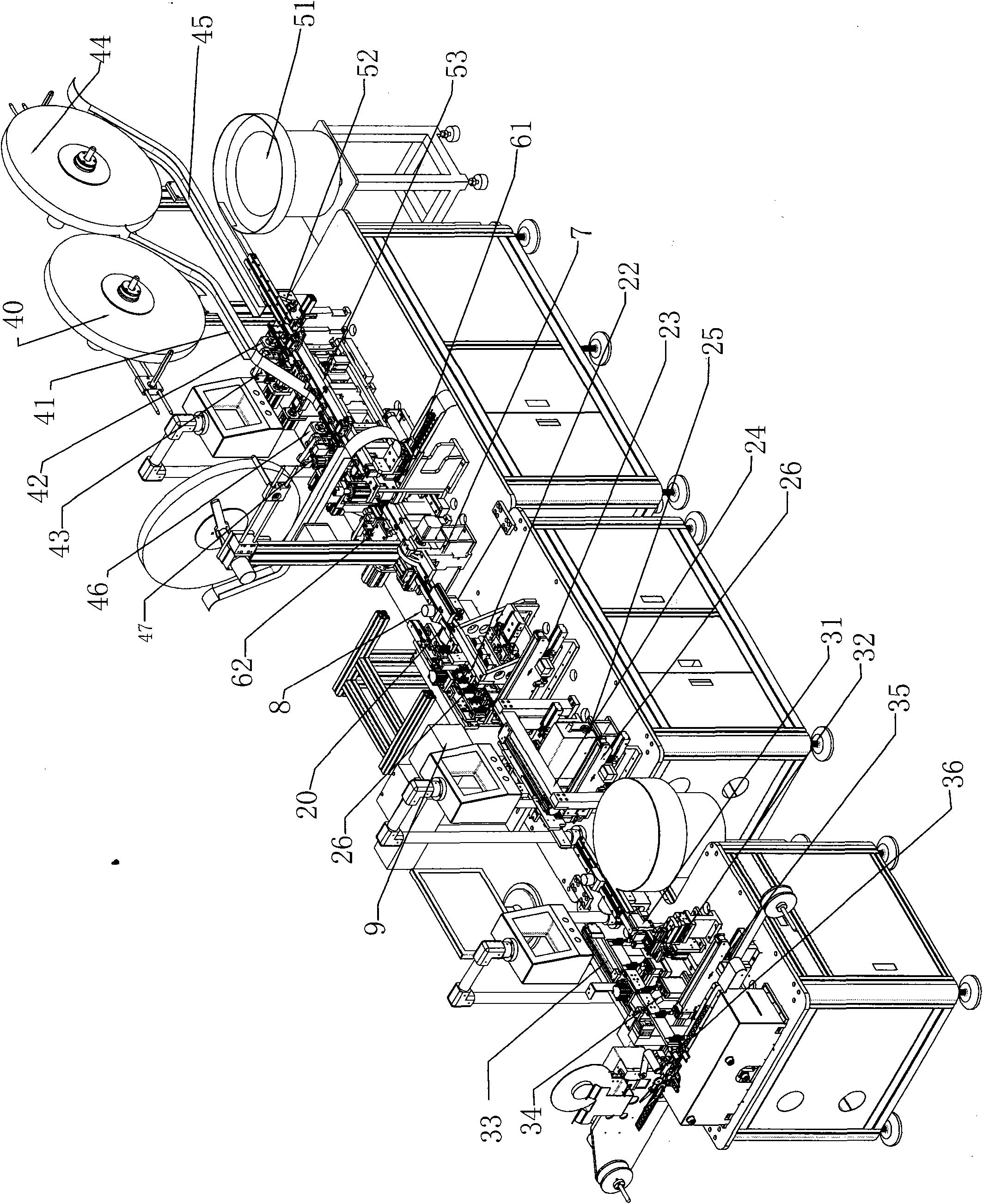
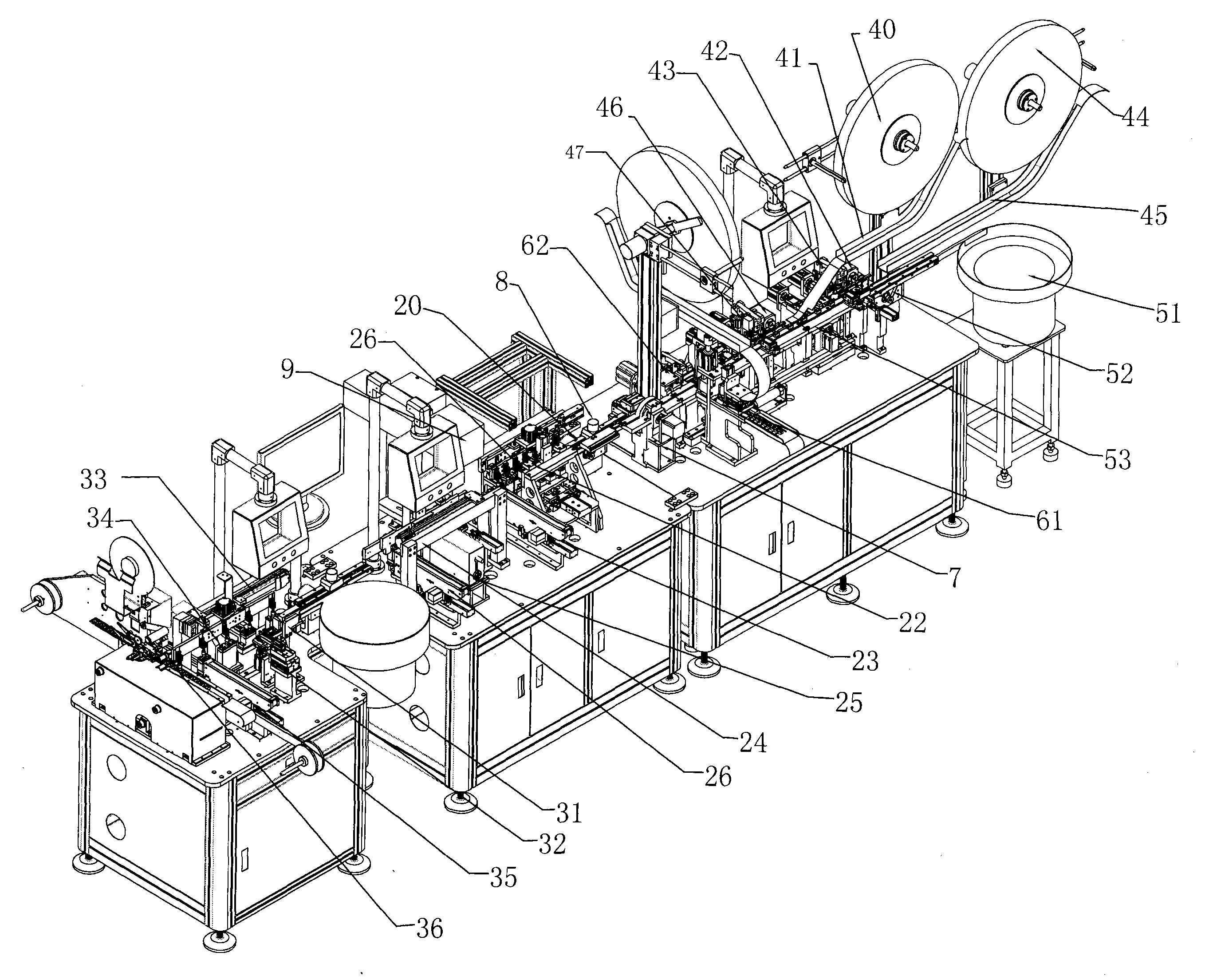
[0015] like figure 1 As shown, a fully automatic production line for HDMI connectors includes a product forming part 1, a product testing part 2, a dust cover installation and product packaging part 3, and the product forming part includes a terminal feeding mechanism 4, a plastic body feeding Feeding mechanism 5 and iron shell feeding mechanism 6;
[0016] The product detection part 2 includes a conduction withstand voltage test mechanism 22, a first CCD detection mechanism 25, a product connection conveyor belt 20, a first defective product screening mechanism 23, a first servo motor displacement mechanism 24, and a second defective product screening mechanism. Mechanism 26, the product connection conveyor belt 20 is arranged between the product forming part 1 and the product detection part 2, after the product connection conveyor belt 20 is sequentially provided with a cylinder suction nozzle displacement mechanism 21, a conduction pressure test mechanism 22, a first The defective product screening mechanism 23 , the first servo motor displacement mechanism 24 , the first CCD detection mechanism 25 and the second defective product screening mechanism 26 .
[0017] The dust cover installation and product packaging part 3 includes a dust cover cylinder displacement mechanism 31, a clamping jaw cylinder assembly dust cover 32, a second servo motor displacement mechanism 33, a second CCD detection mechanism 34, a second CCD detection mechanism 34, a Three defective products screening mechanism 35 and packaging mechanism 36 .
[0018] A product rotation converting mechanism 7 is arranged between the product forming part and the product detecting part.
[0019] A blowing and dusting device 8 is provided on the product connecting conveyor belt.
[0020] The product detection part is also provided with a laser marking machine 9 .
[0021] The terminal feeding mechanism 4 includes a first terminal tray 40 , a first terminal tray 41 , a second terminal tray 44 , a second terminal tray 45 , a first feeding motor 42 , and a first cutting mechanism 43 . , the second stepping motor 46, the second cutting mechanism 47, the first terminal material tray 40, the first terminal material slot 41, the first stepping motor 42 and the first cutting mechanism 43 are arranged in sequence, so The second terminal stock tray 44 , the second terminal stock slot 45 , the second stepping motor 46 and the second cutting mechanism 47 are arranged in sequence.
[0022] The plastic body feeding mechanism 5 includes a vibrating plate 51 , a plastic body conveying belt 52 and a body displacement mechanism 53 arranged in sequence.
[0023] The iron shell feeding mechanism 6 is located at the end of the product forming part 1 , and includes an iron shell feeding tray 61 , an iron shell trough 62 , a cutting and assembling iron shell device 63 and a bending iron shell device 64 arranged in sequence.
[0024] In the present invention, the first defective product screening mechanism, the second defective product screening mechanism, and the third defective product screening mechanism respectively comprise an air cylinder and a conveyor belt.
[0025] The above contents are only preferred embodiments of the present invention, and are not intended to limit the embodiments of the present invention. Appropriate modifications or modifications made by those skilled in the art according to the concept of the present invention shall fall within the protection scope of the present invention. within.

PUM

no PUM

Description & Claims & Application Information

We can also present the details of the Description, Claims and Application information to help users get a comprehensive understanding of the technical details of the patent, such as background art, summary of invention, brief description of drawings, description of embodiments, and other original content. On the other hand, users can also determine the specific scope of protection of the technology through the list of claims; as well as understand the changes in the life cycle of the technology with the presentation of the patent timeline. Login to view more.

Similar technology patents

Automatic glue-dispersion chip mounting machine

Owner:常州摩通机器人科技有限公司

Multi-scale greenhouse environment control system based on crop information fusion

InactiveCN102736596ABeneficial to crop physiology and growth needsIncrease productivity
Owner:NANJING AGRICULTURAL UNIVERSITY

Classification and recommendation of technical efficacy words

Why Eureka
Try Eureka