Uplink power control method and device

A technology for power control and transmit power, applied in the field of uplink power control methods and devices, capable of solving problems such as no longer applicable power control schemes

Inactive Publication Date: 2012-03-14
CHINA ACAD OF TELECOMM TECH
View PDF0 Cites 75 Cited by
  • Summary
  • Abstract
  • Description
  • Claims
  • Application Information

AI Technical Summary

Problems solved by technology

Therefore, subframe-based power con...

Method used


Image

  • Uplink power control method and device
  • Uplink power control method and device
  • Uplink power control method and device

Examples


Embodiment Construction

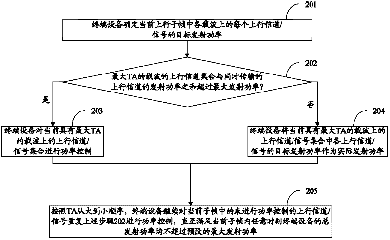
[0043] In the embodiment of the present invention, the terminal device performs power control on the target transmission power of the uplink channel / signal transmitted in the current uplink subframe according to the order of the uplink transmission timing advance from large to small, so as to satisfy the power control. The total transmission power of the terminal device at any time in the current uplink subframe does not exceed the preset maximum transmission power, which ensures that the system can work normally.

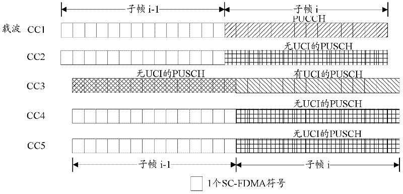
[0044] Preferably, the uplink sending times of the carriers belonging to the same TA group (group) are the same, that is, in the same uplink subframe, the sending times of the uplink channels on the carriers in the TA group are aligned.

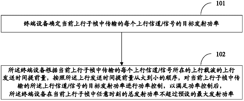
[0045] see figure 1 , the main method flow of uplink power control in this embodiment is as follows:

[0046] Step 101: The terminal device determines the target transmit power of each uplink channel / signal (ie uplink channel or ...


PUM


Abstract

The invention discloses an uplink power control method, which is used for ensuring that a total transmission power of terminal equipment within a sub-frame does not exceed a maximum transmission power by carrying out power control on an uplink channel with different uplink transmission time so as to ensure that a system can work normally. The uplink power control method comprises the following steps of: determining a target emission power of each uplink channel/signal which is transmitted in a current uplink sub-frame by the terminal equipment; and carrying out the power control on the target emission power of each uplink channel/signal which is transmitted in the current uplink sub-frame by the terminal equipment according to uplink transmission time advance amounts of an uplink carrier wave of each uplink channel/signal and a sequence of the uplink transmission time advance amounts from large to small, so that the total emission power of the terminal equipment at the current uplink sub-frame at any time does not exceed a pre-set maximum emission power after the power control is satisfied. The invention further discloses a device for realizing the method.

Description

technical field [0001] The present invention relates to the communication field, in particular to an uplink power control method and device. Background technique [0002] In an LTE (Long Term Evolution, LTE long-term evolution) system, in order to ensure communication quality, one of the main means adopted is uplink power control. Through uplink power control, interference between user equipment (User Equipment, UE) that uses the same resource to send data in adjacent cells can be reduced as much as possible, and the transmission power of the UE can be ensured to be used reasonably. [0003] The uplink power that needs to be controlled mainly includes the transmit power of PUCCH (Physical Uplink Control Channel, physical uplink control channel), the transmit power of PUSCH (Physical Uplink Shared Channel, physical uplink shared channel), and SRS (Souding Reference Signal, sounding reference signal) The transmit power of the channel and the transmit power of the PRACH (Physi...

Claims


Application Information

Patent Timeline
IPC IPC(8): H04W52/14H04W52/36
Inventor 高雪娟林亚男沈祖康潘学明
Owner CHINA ACAD OF TELECOMM TECH
Why Eureka
Try Eureka