
Thin-wall frame body milling vacuum repressing type clamp device

A fixture device and frame body technology, applied in positioning devices, clamping, manufacturing tools, etc., can solve the problems of local stress on parts, difficulty in meeting design requirements for parts quality, and elastic deformation of parts, so as to improve product production quality and overcome The effect of elastic deformation

Inactive Publication Date: 2012-03-21
HARBIN JIANCHENG GRP
View PDF6 Cites 6 Cited by
  • Summary
  • Abstract
  • Description
  • Claims
  • Application Information

AI Technical Summary

Problems solved by technology

[0003] The purpose of the present invention is to provide a thin-walled frame milling vacuum recompression fixture device to solve the problem that the clamps used in the processing of thin-walled frame parts cause local stress on the parts, which easily causes elastic deformation of the parts and the quality of the parts is very low. Difficult to meet design requirements

Method used


Image

  • Thin-wall frame body milling vacuum repressing type clamp device
  • Thin-wall frame body milling vacuum repressing type clamp device
  • Thin-wall frame body milling vacuum repressing type clamp device

Examples


specific Embodiment approach 1

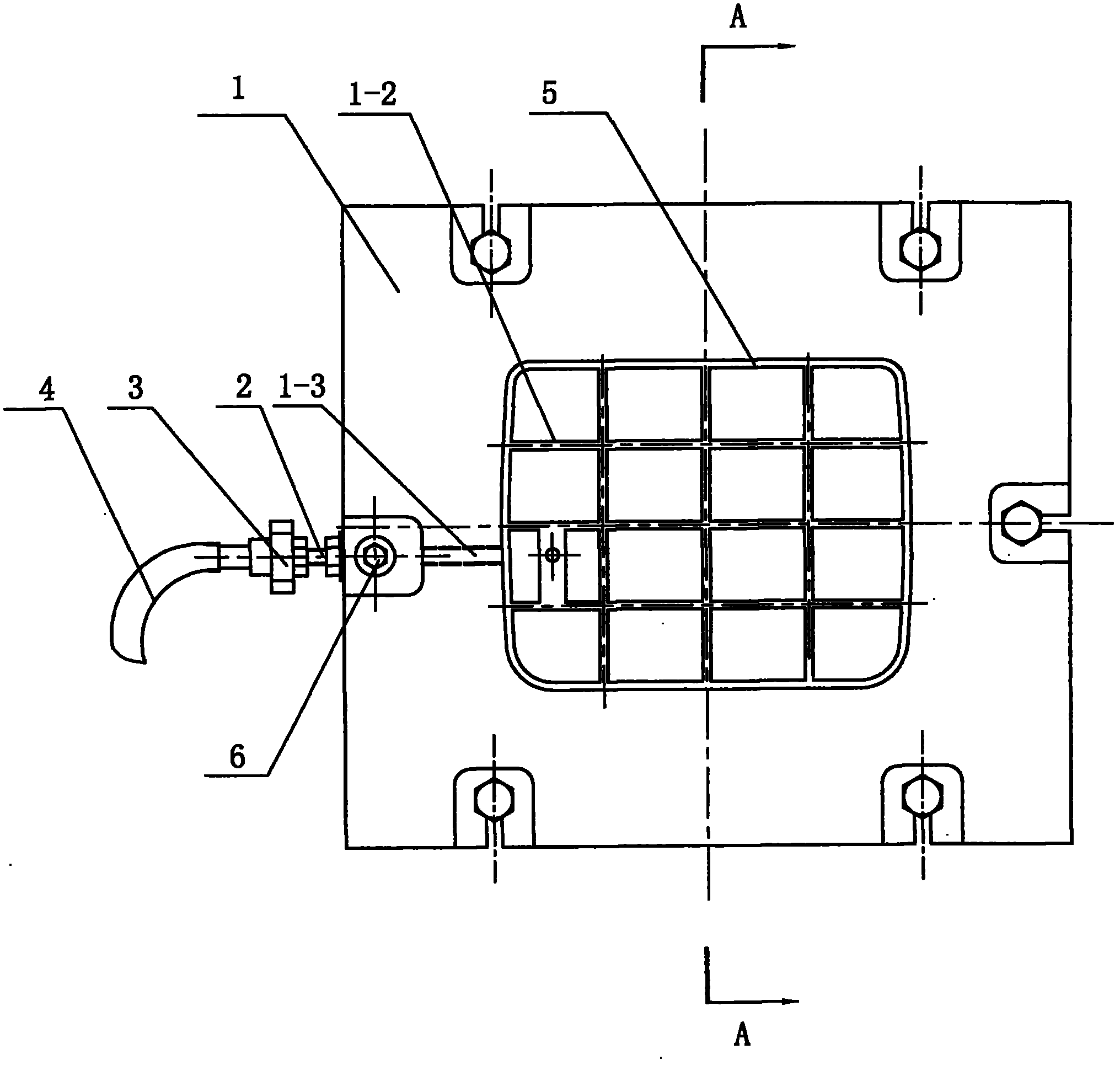
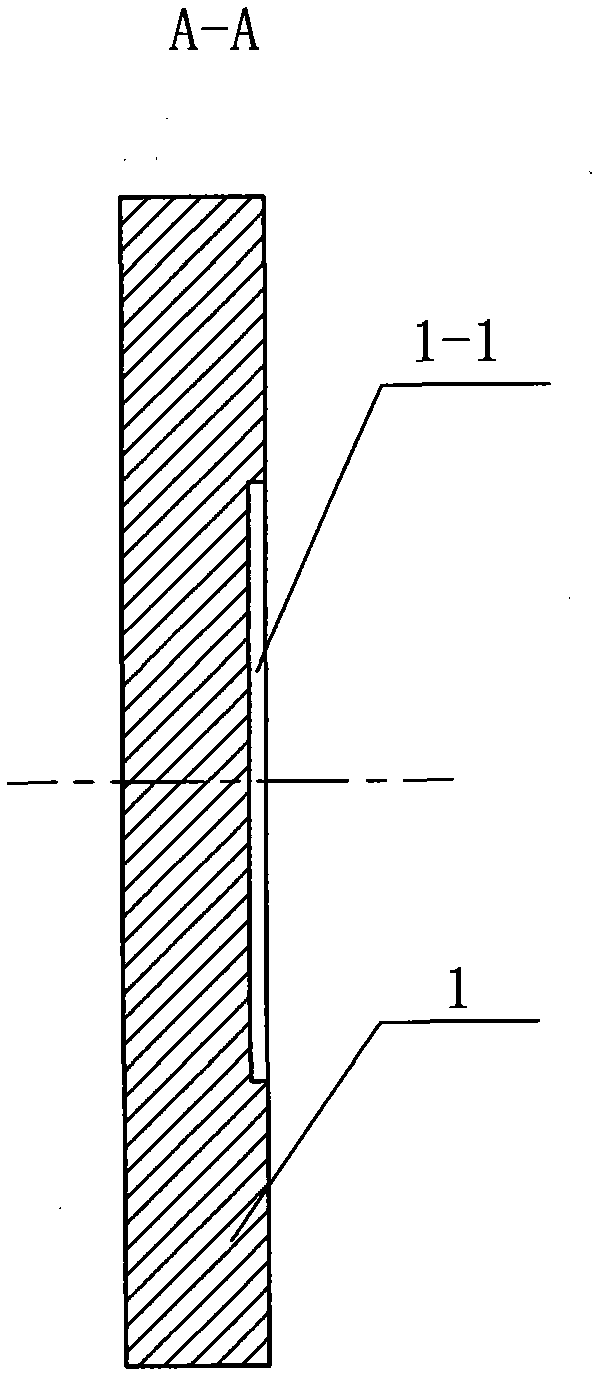
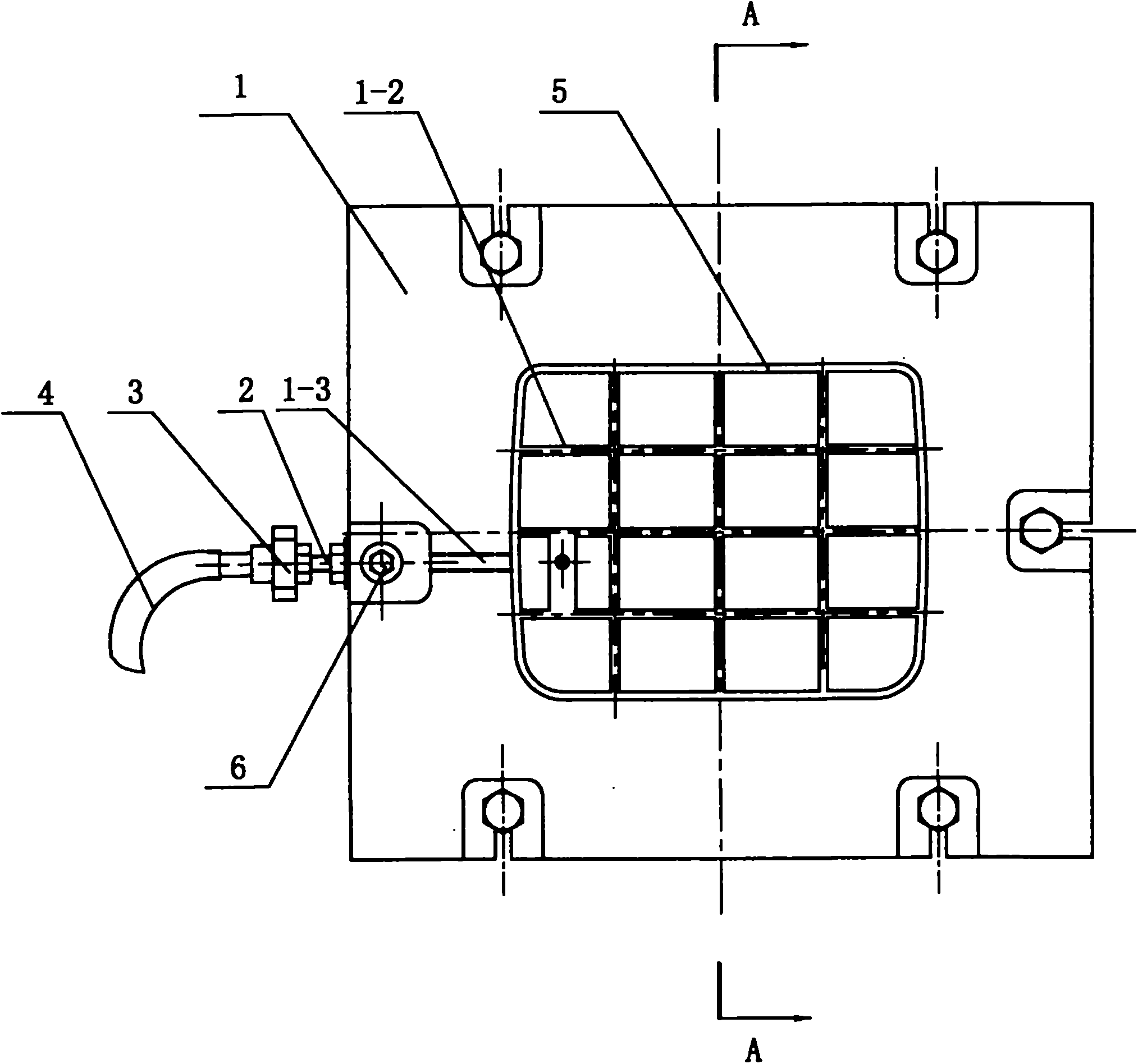
[0007] Specific implementation mode one: combine figure 1 and figure 2 Describe this embodiment, the fixture device of this embodiment comprises fixture thin plate 1, hollow stud 2, pipe joint 3 and vacuum pump 4, and the groove 1 corresponding to thin-walled frame 5 is opened on the upper surface of fixture thin plate 1- 1. The groove 1-1 is provided with a plurality of channels 1-2 that intersect horizontally and vertically. The upper surface of the clamp sheet 1 is closely attached to the lower surface of the thin-walled frame 5, and the thin-walled frame 5 is located in the groove Above 1-1, the side wall of the fixture sheet 1 has a through hole 1-3, the through hole 1-3 communicates with the channel 1-2, and one end of the hollow stud 2 is threadedly connected with the through hole 1-3 of the fixture sheet 1 , the other end of the hollow stud 2 is threadedly connected to one end of the pipe joint 3 , and the other end of the pipe joint 3 communicates with the vacuum pu...

specific Embodiment approach 2

[0008] Specific implementation mode two: combination figure 2 To describe this embodiment, the clamp device of this embodiment further includes a hold-down bolt 6 , and the hold-down bolt 6 fixes the hollow stud 2 and the clamp sheet 1 together. Strengthen the connection between the hollow stud 2 and the clamp sheet 1. Other components and connections are the same as those in the first embodiment.

[0009] Working principle: Screw the hollow stud into the through hole 1-3 of the fixture sheet 1 to ensure tight thread connection, fix the fixture sheet 1 on the working platform, and cover the thin-walled frame 5 on the groove 1-3 of the fixture sheet 1 1, to ensure that the assembly is tight and the joint surface is tightly bonded, use the vacuum pump 4 to evacuate the middle groove of the thin-walled frame 5 and the fixture sheet 1, so that it is firmly fixed by the air pressure on the upper surface of the thin-walled frame 5 It is fixed on the fixture thin plate 1, so that ...


PUM


Abstract

The invention provides a thin-wall frame body milling vacuum repressing type clamp device, which relates to a clamp device and aims at the problems that the existing clamp used for processing thin-wall frame body type parts can cause the local stress of parts, the parts can easily generate elastic deformation, and the quality of the parts is difficult to reach the design requirements. The clamp device comprises a clamp thin plate, a hollow stud, a pipe joint and a vacuum pump, wherein a groove corresponding to the thin-wall frame body is arranged on the upper surface of the clamp thin plate, a plurality of passages crossed in transverse and vertical directions are arranged in the groove, the upper surface of the clamp thin plate is tightly pasted with the lower surface of the thin wall frame body, in addition, the thin wall frame body is positioned above the groove, the side wall of the clamp thin plate is provided with a through hole, the through hole is communicated with the passages, one end of the hollow stud is connected with the through hole of the clamp thin plate through screw threads, the other end of the hollow stud is connected with one end of the pipe joint through screw threads, and the other end of the pipe joint is communicated with the vacuum pump. The thin-wall frame body milling vacuum repressing type clamp device is used for installing and clamping the processed thin-wall frame body.

Description

technical field [0001] The invention relates to a clamp device. Background technique [0002] When processing thin-walled frame parts, the multi-point fixing method of the pressure plate is often used for clamping. This clamping method causes the parts to be partially stressed, and it is easy to cause elastic deformation of the parts. After deformation, it is difficult to correct the shape and the quality of the parts is difficult to meet the design requirements. . Contents of the invention [0003] The purpose of the present invention is to provide a thin-walled frame milling vacuum recompression fixture device to solve the problem that the clamps used in the processing of thin-walled frame parts cause local stress on the parts, which easily causes elastic deformation of the parts and the quality of the parts is very low. Difficult to meet design requirements. [0004] The technical solution adopted by the present invention to solve the above-mentioned technical problem...

Claims


Application Information

Patent Timeline
Patent Type & Authority Applications(China)
IPC IPC(8): B23Q3/06
Inventor 于晶闫明春李利华
Owner HARBIN JIANCHENG GRP
Features
  • Generate Ideas
  • Intellectual Property
  • Life Sciences
  • Materials
  • Tech Scout
  • Unparalleled Data Quality
  • Higher Quality Content
  • 60% Fewer Hallucinations
Learn More