Hydraulic locking device for scraping tumbling mill

A locking device, scraping and rolling technology, which is applied in the direction of metal processing machinery parts, maintenance and safety accessories, metal processing equipment, etc., can solve the problems of affecting the processing progress and low efficiency, and achieve high production efficiency and novel structure Effect

Inactive Publication Date: 2012-03-21
CHANGZHOU WUJIN WUYANG TEXTILE MACHINERY
View PDF0 Cites 0 Cited by
  • Summary
  • Abstract
  • Description
  • Claims
  • Application Information

AI Technical Summary

Problems solved by technology

The original locking mechanism adopts the mechanical structure of bolts and splints. Every time the position of the oil feeder is adjusted, the bolts and splints must be disassembled and tightened once, which affects the processing progress to a certain extent and is inefficient.

Method used


Image

  • Hydraulic locking device for scraping tumbling mill
  • Hydraulic locking device for scraping tumbling mill
  • Hydraulic locking device for scraping tumbling mill

Examples


Embodiment Construction

[0011] In order to be understood that the present invention is clearer, the present invention will be further described below in conjunction with accompanying drawing:

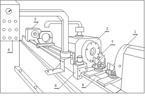
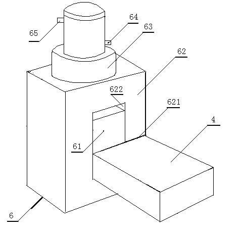
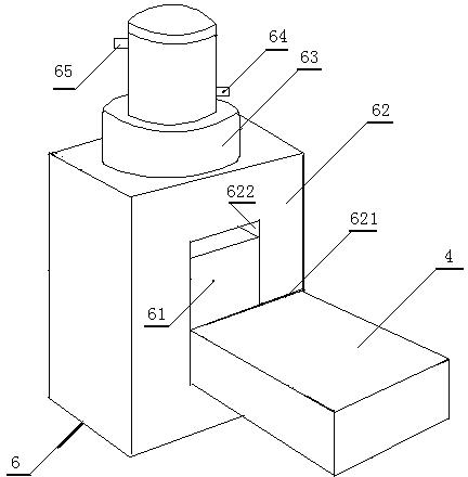
[0012] Such as figure 1 with 2 As shown, the present invention is suitable for a hydraulic locking device for scraping and tumbling machines, including a precision machine tool, on which there is a guide rail 4, on which a headstock is installed in sequence and coaxially 3. The oil feeder 2 and the tailstock box 1, the tailstock box 1 is fixedly connected to the guide rail 4, the oil feeder 2 slides along the guide rail 4 with the traction of the first conveyor and is locked by the locking mechanism , the head box 3 slides along the guide rail 4 with the traction of the second conveyor, and a left hydraulic locking device 6 and a right hydraulic locking device 7 are installed on both sides of the oil feeder 2, and the left hydraulic locking device 6 and the right hydraulic locking device 7, which are geometr...


PUM


Abstract

The invention discloses a hydraulic locking device for a scraping tumbling mill, which comprises a precision machine tool, wherein a guide rail is arranged on the machine tool; a lathe head box, an oil supplier and a tail seat box are arranged on the guide rail coaxially in turn; the tail seat box is fixedly connected with the guide rail; the oil supplier is driven by a first conveyor to slide along the guide rail and is locked by the locking mechanism; and the lathe head box is driven by a second conveyor to slide along the guide rail, and a left hydraulic locking device and a right hydraulic locking device are arranged on the two sides of the oil supplier. The oil pipe A of each hydraulic locking device is electrically connected with a hydraulic device and a digital control device, and the flow direction in an oil path is controlled by an instruction given by the digital control device according to a program, so the hydraulic locking devices change between locking and releasing. The hydraulic locking device is novel in structure, does not need manual detachment, is simple convenient and has high production efficiency.

Description

technical field [0001] The invention relates to a locking device, in particular to a hydraulic locking device suitable for scraping and rolling machines. Background technique [0002] The scraping and rolling machine is a precision machine tool for processing the inner hole of the hydraulic cylinder. In order to adapt to the diversity of the inner hole of the hydraulic cylinder, the types of the rolling machine are also diverse. The original locking mechanism is a mechanical structure of bolts and splints. Every time the position of the oil feeder is adjusted, the bolts and splints must be disassembled and tightened once, which affects the processing progress to a certain extent and is inefficient. Contents of the invention [0003] In order to solve the above problems, the present invention provides a simple, convenient and highly efficient hydraulic locking device for a scraping and rolling machine. [0004] In order to achieve the above object, the present invention is...

Claims


Application Information

Patent Timeline
Patent Type & Authority Applications(China)
IPC IPC(8): B23Q11/00
Inventor 王敏其王水胡小伟
Owner CHANGZHOU WUJIN WUYANG TEXTILE MACHINERY
Why Eureka
Try Eureka