Blow mold

一种吹塑模、吹塑机的技术,应用在吹塑模领域,能够解决不可控变形等问题,达到快速循环次数、轻质量、紧凑尺寸的效果

Inactive Publication Date: 2012-03-21
KRONES AG
View PDF4 Cites 7 Cited by
  • Summary
  • Abstract
  • Description
  • Claims
  • Application Information

AI Technical Summary

Problems solved by technology

Because the locking pressure of the collar acts only in locally limited areas of the two mold support shells, there is a risk that under the forces caused by the blow molding operation, uncontrolled deformations will occur on the mold parts, thereby Mold parting lines are undesirably displayed in at least some areas of manufactured containers

Method used


Image

  • Blow mold
  • Blow mold
  • Blow mold

Examples


Embodiment Construction

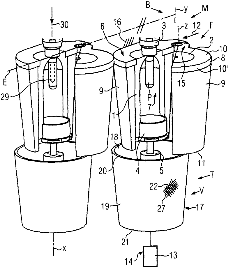
[0031] figure 1 An open blow mold F is shown, which is arranged on the adjacent blow molding station of the blow rotor B of the blow molding machine M. The blowing rotor B can be driven in rotation about the blowing rotor axis Y. The blow mold F comprises a mold parting surface E which, in the exemplary embodiment shown, is arranged radially with respect to the blow rotor axis Y. FIG. Each blow mold has a blow mold axis X. As an alternative, the blow mold can be used in a fixed blow station of the blow molding machine. Each blow mold F is used to manufacture a container (e.g. a plastic bottle) from a preform P, for example by a blow molding operation or a stretch blow molding operation, wherein the preform P is loaded into the open blow mold, closed and The blow mold is locked, followed by the blow molding operation, and then the blow mold is opened to be able to remove the produced container.

[0032] In the illustrated embodiment, the blow mold comprises: mold parts 1, 2...


PUM


Abstract

A procedure for controlling actuators within an on-board power system, which provides different operating voltages and temporal on-board power voltage changes. The actuator or actuators are controlled with different pulse-width modulated control signals, whereby the pulse-width and the cycle duration of the control signals can be adjusted independent of each other and are adjusted independent of the actually applied on-board power voltage. Control signals for the actuators can be specified by a control unit. The actuator or actuators can be controlled with the aid of the control unit by different pulse-width modulated control signals, whereby the pulse-width and the cycle duration of the control signals can be adjusted independent of each other; and the control unit provides devices for detecting the actually applied on-board power voltage and driver units.

Description

technical field [0001] The invention relates to a blow mold according to the preamble of patent claim 1 . Background technique [0002] In blow molding or stretch blow molding, at least the mold parts (mold halves) for shaping the wall region of the container are usually accommodated in a mold support housing. The mold support shell usually also functions to control the temperature of the blow mold. To this end, channels through which the temperature control medium (water, oil) flows are formed in the mold support housing. Usually, a two-part mold support is provided for fixing the mold support shell, which provides a retaining function to the mold support shell, mainly to withstand the forces during the blow molding operation. The task of absorbing forces requires in particular a very robust design of the supports of the mold support, which also serve to open and close the blow mould. Furthermore, in many cases locking elements are provided in the front region of the mod...

Claims


Application Information

Patent Timeline
Patent Type & Authority Applications(China)
IPC IPC(8): B29C49/48B29C49/56
CPCB29C49/56B29C33/26B29C49/36B29C49/42B29C49/4236B29C49/4823B29C2049/4892B29C49/122B29C2049/5633B29C2049/5635B29C2049/5661
Inventor 克里斯蒂安·施托伊贝尔托马斯·阿尔布雷希特
Owner KRONES AG
Why Eureka
Try Eureka