Hinge device and portable device

A technology for hinge devices and fixed parts, which is applied in the field of hinge devices and portable equipment, and can solve the problems of early wear and tear of two plane parts

Inactive Publication Date: 2009-07-29
SUGATSUNE IND CO LTD
View PDF4 Cites 0 Cited by
  • Summary
  • Abstract
  • Description
  • Claims
  • Application Information

AI Technical Summary

Problems solved by technology

As a result, there is a problem that the fixing member and the two flat parts connecting the cylindrical part are prone to early wear and tear.

Method used


Image

  • Hinge device and portable device
  • Hinge device and portable device
  • Hinge device and portable device

Examples


Embodiment Construction

[0030] Hereinafter, the best example for implementing the present invention will be described with reference to the drawings.

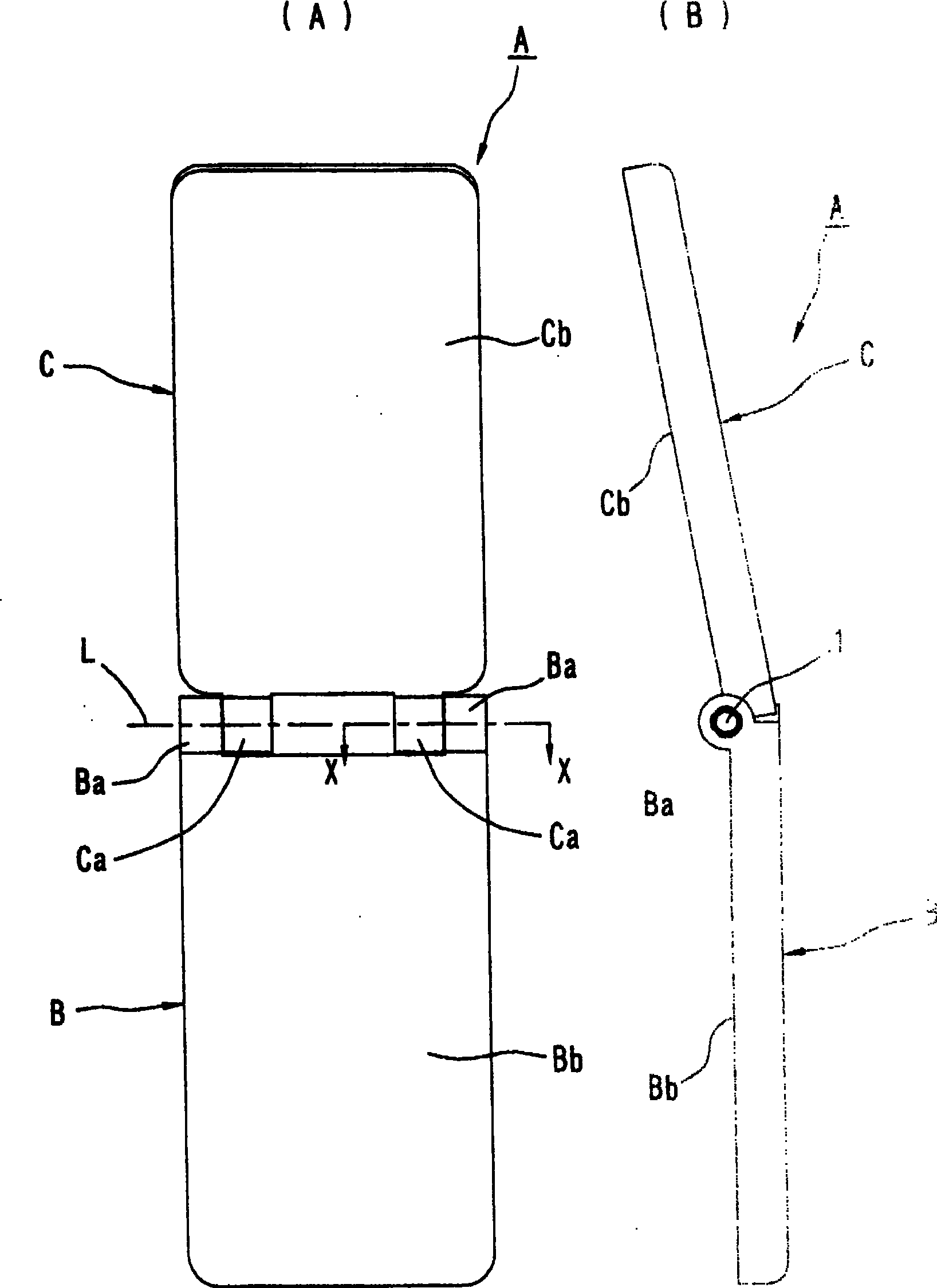
[0031] figure 1 (A) and (B) indicate the use of the hinge device 1 of the present invention (refer to Figure 2 ~ Figure 4 ) Mobile phone A. The mobile phone A has a transmission side housing (second housing) B and a reception side housing (first housing) C. Two connecting cylindrical portions (second connecting cylindrical portions) Ba are formed at one end of the transmission side housing B in a state in which their axes are aligned. Two connecting cylindrical portions (first connecting cylindrical portions) Ca are also formed at one end of the receiving-side housing C in a state in which the axes of each other are aligned. The two connecting cylindrical parts Ca and Ca are inserted between the two connecting cylindrical parts Ba and Ba. The two adjacent connecting cylinders (the two connecting cylinders on the right side in Figure (A)) Ba and Ca can ...


PUM


Abstract

The invention relates to a hinge device and a portable device using the hinge device. To provide a hinge device capable of preventing looseness between a transmitting-side housing and a receiving-side housing of a cellular phone for a long period of time. Planar portions (5f), (5f) extending parallel to the rotation axis (L) are formed on the outer peripheral surface of a fixing member (5) fixed in position to a receiver-side housing (not shown). A flat plate portion (8a) extending parallel to the rotation axis (L) and substantially in contact with the flat portion (5f) is formed on the cam member (8) made of metal. By engaging the flat plate portion (8a) with the inner peripheral surface of the receiver-side housing, the cam member (8) is non-rotatably coupled to the receiver-side housing.

Description

Technical field [0001] The present invention relates to a hinge device and a portable device using the hinge device. The hinge device is used to rotatably connect two components of a portable device, such as a transmitting side housing and a receiving side housing of a mobile phone. Background technique [0002] As described in Patent Document 1 below, a hinge device that generally rotatably connects the transmitting side housing and the receiving side housing of a mobile phone has: a hinge device that is non-rotatably fitted to the connecting cylinder of the transmitting side housing The fixed member and the movable member that is non-rotatably fitted to the connecting tube portion of the receiving side housing. The fixed member and the movable member are rotatably connected. As a result, the receiving-side housing is rotatably connected to the transmitting-side housing. The rotating range of the receiver-side housing is usually limited between the folded position and the talkin...

Claims


Application Information

Patent Timeline
Patent Type & Authority Patents(China)
IPC IPC(8): F16C11/04H04M1/02
Inventor 石谷和征
Owner SUGATSUNE IND CO LTD
Why Eureka
Try Eureka