Winder station and operation method for station

A winding machine and station technology, which is applied in the directions of transportation and packaging, conveying filamentous materials, thin material processing, etc., and can solve problems such as high energy consumption

Inactive Publication Date: 2012-03-21
SAURER GERMANY GMBH & CO KG
View PDF7 Cites 3 Cited by
  • Summary
  • Abstract
  • Description
  • Claims
  • Application Information

AI Technical Summary

Problems solved by technology

However, in order to maintain negative pressure, high energy consumption is required

Method used


Image

  • Winder station and operation method for station
  • Winder station and operation method for station
  • Winder station and operation method for station

Examples


Embodiment Construction

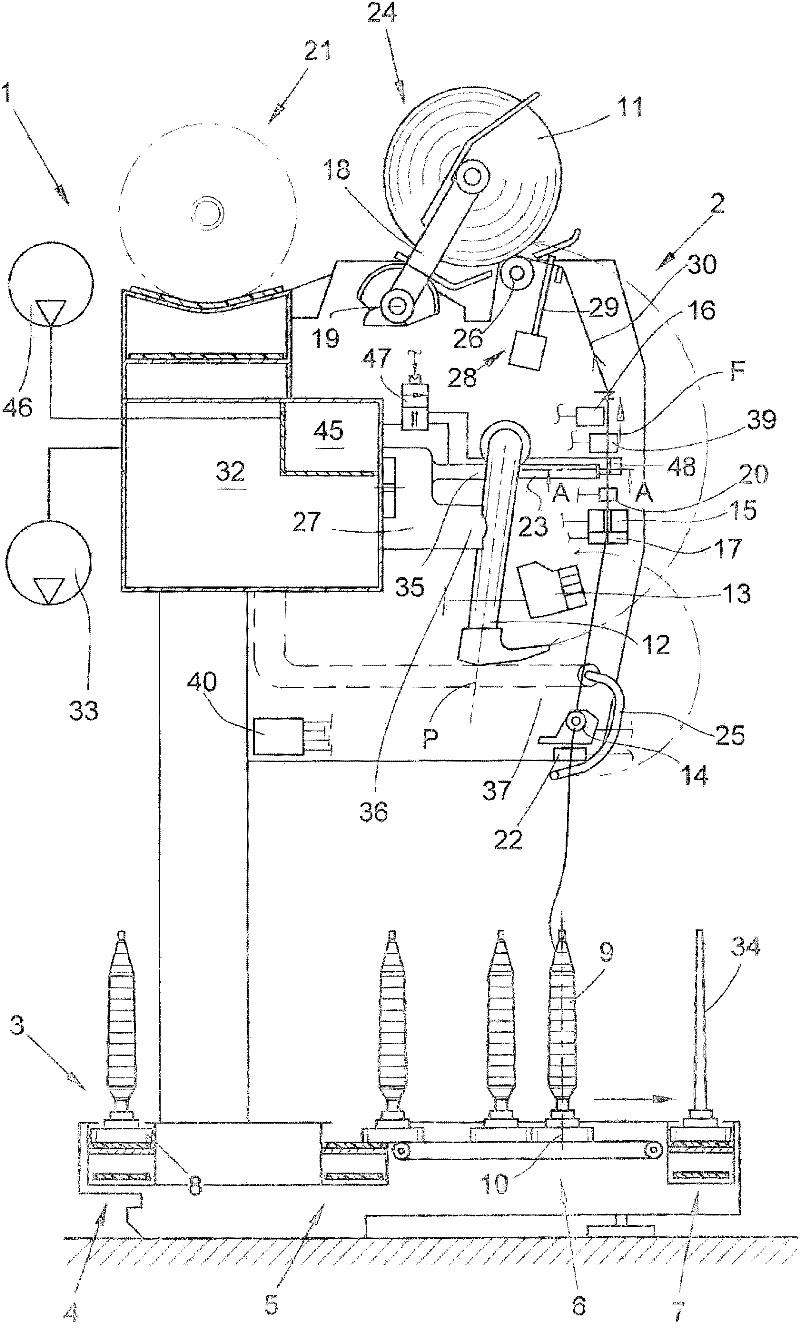
[0019] figure 1 The station 2 of the winder 1, which in this embodiment is a so-called automatic crosswinding winder, is shown in a schematic side view during the winding process. Such an automatic cross-winding winder 1 has a number of identical stations 2 between its end frames (not shown), so-called winding positions.

[0020] In these winding positions 2, the feeding bobbins, which are generally produced on ring spinning machines with relatively small amounts of yarn material 9, are rewound into large packages as is well known and therefore not described in detail. The cross-wound bobbin 11. The produced cross-wound bobbins 11 are then handed over to the cross-wound bobbin conveyor 21 along the length of the machine by means of an automatically operating service unit, such as a cross-wound bobbin changer, and sent to the machine end side. Package loading station, etc.

[0021] Furthermore, this automatic cross-wound winder is either equipped with a circular magazine in ...


PUM


Abstract

The invention relates to a station (2) for a winder (1), the station is provided with a yarn capturing nozzle (23) with negative pressure be capable of being applied, the yarn capturing nozzle is arranged near a yarn movement path (31), and a through opening (42) of the yarn capturing nozzle aligns with the yarn movement path (31). According to the invention, an j The device (14) has an input (141) connected with an input connection (21), an injection device (40) used for generating blow air shock is disposed near the yarn movement path (31), so as to make a through opening (51) of the injection device (48) not only be aligned with yarns (30) in the yarn movement path (31), but also be aligned with a through opening (42) of the yarn capturing nozzle (23), and a mechanism (47, 40) used for triggering blow air shock according to requirement is disposed. The invention also relates to an operation method for the station (2).

Description

technical field [0001] The invention relates to a winder station having a yarn catcher which can be applied with negative pressure, the yarn catcher being arranged in the vicinity of the yarn moving path and the opening of the yarn catcher being aligned with the yarn moving path. Furthermore, the present invention relates to a method of operating the station. Background technique [0002] A winder winds yarn from unwinding packages such as cops into winding packages, mostly cross-wound packages. In order to perform the winding operation, the station of such a winder has various yarn monitoring mechanisms, yarn handling mechanisms and yarn handling mechanisms in the region of the yarn travel path. Generally, a so-called yarn catcher is provided in the yarn travel path at each winding position. The yarn catcher is a tube that can withstand suction and is used to suck in and hold the yarn end in the event of an occasional yarn break. The yarn catcher also sucks in stray yarn...

Claims


Application Information

Patent Timeline
Patent Type & Authority Applications(China)
IPC IPC(8): B65H67/08
CPCB65H54/707B65H54/702B65H54/88B65H67/081B65H2701/31
Inventor U·霍尔特沃尔夫冈·伊姆恩迈克尔·赖曼汉斯-冈特·威德肖温
Owner SAURER GERMANY GMBH & CO KG
Why Eureka
Try Eureka