Pin moving device, movable connecting structure and suspension hook structure

A technology for moving devices and pin shafts, which is applied in the field of machinery, can solve the problems of difficult installation of pin shafts and high friction, and achieve the effects of small installation difficulty, reduced friction, and labor-saving installation

Active Publication Date: 2012-03-21
XCMG CONSTR MACHINERY
View PDF6 Cites 6 Cited by
  • Summary
  • Abstract
  • Description
  • Claims
  • Application Information

AI Technical Summary

Problems solved by technology

[0019] The purpose of the present invention is to propose a pin shaft moving device, a movable connection structure provided with the pin shaft moving device, and a hook structure provided with the movable connection structure, which solves the problem of the installation of the pin shaft and the pin shaft that needs to be installed in the prior art. The friction between the inner walls of the holes is relatively large, resulting in the technical problem that the pin shaft is difficult to install

Method used


Image

  • Pin moving device, movable connecting structure and suspension hook structure
  • Pin moving device, movable connecting structure and suspension hook structure
  • Pin moving device, movable connecting structure and suspension hook structure

Examples


Embodiment 1

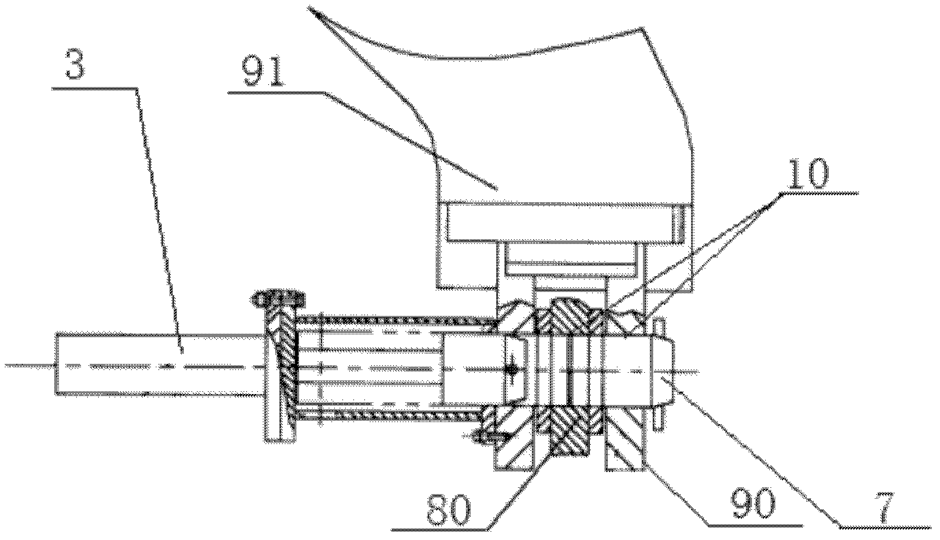
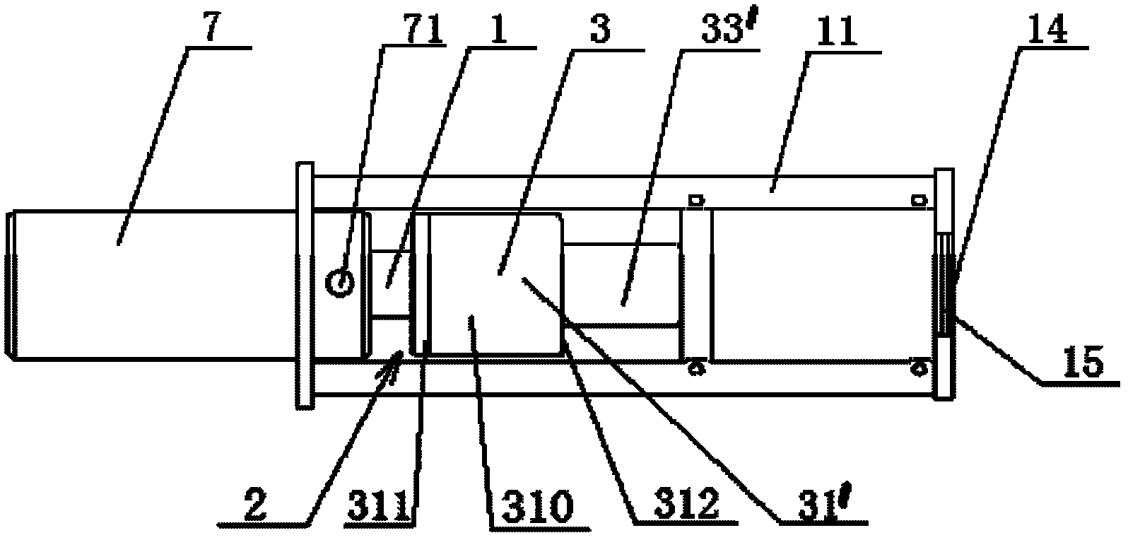
[0048] Such as image 3 , Figure 4 and Figure 5 As shown, the pin shaft moving device provided by the embodiment of the present invention includes a pin shaft 7, a rotary power device 2 and a transmission member 1 arranged in the rotary power device 2, wherein:

[0049] The pin shaft 7 is fixedly connected to the transmission part 1, or the pin shaft 7 and the transmission part 1 are in an integrated structure;

[0050] The rotating power device 2 is used to drive the transmission part 1 and the pin shaft 7 to rotate along the circumferential direction of the pin shaft 7, and simultaneously drive the transmission part 1 and the pin shaft 7 to advance or retreat along the axial direction of the pin shaft 7;

[0051] Both the pin shaft 7 and the transmission member 1 are coaxial (the axis refers to the rotation axis of the pin shaft 7 and the transmission member 1 ).

[0052] The axial direction refers to the direction extending along the axis of the pin shaft 7 and other c...

Embodiment 2

[0091] Such as Figure 8 As shown, this embodiment is basically the same as Embodiment 1, and the difference is that in this embodiment, the circumferential power mechanism 22 also includes a guide chamber 33, but a third through hole 63 is opened on the guide chamber 33, and the guide chamber 33 is provided with a third through hole 63 for guiding The chamber 33 communicates with the power chamber 31 through the first through hole 61 opened in the first axial side wall 311;

[0092] The ball nut 41 is fixed on the inner wall of the first through hole 61 , and the transmission member 1 passes through the ball nut 41 and the third through hole 63 .

[0093] It can be seen from the above that the main difference between this embodiment and embodiment 1 is that the relative position of the guide chamber 33 and the transmission member 1 is different from that of embodiment 1, but the same as embodiment 1, this embodiment can also realize the above-mentioned invention The technica...

Embodiment 3

[0095] Such as Figure 9 As shown, this embodiment is basically the same as Embodiment 1, and the difference is that the circumferential power mechanism 22 in this embodiment includes a guide chamber 33 and an external thread 42 provided on the transmission member 1, wherein:

[0096] The guide chamber 33 communicates with the power chamber 31 through the second through hole 62 opened on the second axial side wall. The part of the transmission member 1 provided with the external thread 42 passes through the second through hole 62, and the outer thread 42 on the transmission part 1 passes through the second through hole 62, and the outer The thread 42 cooperates with the internal thread provided on the inner wall of the guide chamber 33 and / or the second through hole 62 .

[0097] Due to the helix angle of the thread, when one of the two parts connected by the thread moves linearly, it must rotate at the same time, so the external thread 42 on the transmission member 1 and the ...


PUM


Abstract

The invention discloses a pin moving device which comprises a pin, a rotary power unit and a driving member arranged in the rotary power unit, wherein, the pin and the driving member are in fixed connection, or the pin and the driving member are of a one-piece structure, the rotary power unit is used for driving the driving member and the pin to rotate along a circumferential direction of the pin and simultaneously driving the driving member and the pin to move forward or backward along the axial direction of the pin, and the pin and the driving member are arranged along a coaxial line. The invention also discloses a movable connecting structure having the pin moving device and a suspension hook structure. The invention enables the technical problem in the prior art that it is difficult to install a pin because a great frictional force between the pin and the inner wall of an installing hole needing to be installed with the pin to be overcome, and enables the problem that a large-size and great-weight suspension hook is prone to making integral transportation of the suspension hook exceed national restrictions on transportation weight and size to be overcome.

Description

technical field [0001] The invention relates to the field of mechanical technology, and in particular to a pin shaft moving device, a movable connection structure provided with the pin shaft moving device, and a hook structure provided with the movable connection structure. Background technique [0002] The pin shaft can not only statically connect two or more connected parts, but also move relative to the connected parts, so it is widely used in the hinge of two or more parts. [0003] Crawler crane is a kind of mechanical device that uses more pins. For example, pins are used in the hook structure and crawler structure of crawler cranes. [0004] Such as figure 1 As shown, the hook structure of the existing crawler crane includes a hook, a hook pulley block frame 8, a supporting side plate frame 9 and a pin shaft 7, wherein: [0005] Flexible connection between suspension hook (not shown in the figure) and support side plate frame 9; [0006] Mounting holes 10 are provi...

Claims


Application Information

Patent Timeline
Patent Type & Authority Applications(China)
IPC IPC(8): B66C1/34B62D55/08
Inventor 章琢赵波孙丽孙影
Owner XCMG CONSTR MACHINERY
Why Eureka
Try Eureka