Pavement milling machine

A milling machine and frame technology, applied in the field of road equipment, can solve problems such as oil cylinder leakage, reduced safety and reliability of road milling machines, and pipe bursts in hydraulic systems, so as to enhance safety and reliability and reduce hydraulic pressure. Effect of internal oil leakage and risk of cylinder subsidence

Active Publication Date: 2012-03-21
ZOOMLION HEAVY IND CO LTD
View PDF5 Cites 6 Cited by
  • Summary
  • Abstract
  • Description
  • Claims
  • Application Information

AI Technical Summary

Problems solved by technology

This makes, on the one hand, the pressure in the oil cylinder is high during the working period, which may easily cause the hydraulic system t

Method used


Image

  • Pavement milling machine
  • Pavement milling machine
  • Pavement milling machine

Examples


Embodiment Construction

[0031] Specific embodiments of the present invention will be described in detail below in conjunction with the accompanying drawings. It should be understood that the specific embodiments described here are only used to illustrate and explain the present invention, and are not intended to limit the present invention.

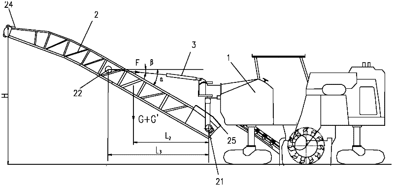
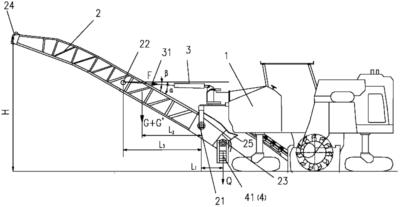
[0032] In the present invention, in the case of no contrary description, the used orientation words such as "up and down" are usually defined under the normal use of the road milling machine provided by the present invention, that is figure 1 and figure 2 direction shown.

[0033] Such as figure 2 As shown, the present invention provides a road milling machine, which includes a frame 1, a conveyor belt conveyor 2 and a lifting cylinder 3, and the conveyor belt conveyor 2 has an input end 25 and an output end 24 arranged oppositely, The conveyor belt conveyor 2 is hinged on the frame 1 through the first hinge point 21, one end of the lifting cylinder 3 is hi...


PUM


Abstract

The invention discloses a pavement milling machine, which comprises a frame (1), a material filling belt conveyor (2) and a lifting oil cylinder (3), an input end (25) and an output end (24) which are relatively arranged in the material filling belt conveyor, the material filling belt conveyor is hinged to the frame through a first hinge point (21), one end of the lifting oil cylinder is hinged to the frame, the other end of the lifting oil cylinder is hinge to the material filling belt conveyor through a second hinge point (22), and the second hinge point is positioned over the first hinge point, the first hinge point is positioned between the second hinge point and the input end of the material filling belt conveyor. The first hinge point enables relative movement to the input end upwardly, The own weight of the input end is capable of effectively mitigating the load of the lifting oil cylinder according to the lever principle, so that the pressure of hydraulic oil in the cylinder is reduced, the risks of inner leakage of hydraulic oil and settlement of the oil cylinder can be reduced, thereby the security and reliability of the pavement milling machine are substantially enhanced.

Description

technical field [0001] The invention relates to a road surface equipment, in particular to a road surface milling machine. Background technique [0002] In road maintenance construction, road milling machines are widely used. Its working process is as figure 1 As shown, the road surface is first milled by the milling drum of the milling machine, and then the road surface waste is thrown onto the collecting belt through the throwing plate on the milling drum, and then the road surface waste is transported to the conveyor belt conveyor by the collecting belt The input end 25 is transported by the conveyor belt conveyor and delivered to the loading truck through the output end 24. [0003] Among them, due to the height of the loading truck, the conveying belt conveyor needs to meet the loading height H of the road waste, which requires the configuration of the lifting cylinder 3, one end of the lifting cylinder 3 is hinged with the frame 1 of the milling machine, and the othe...

Claims


Application Information

Patent Timeline
IPC IPC(8): E01C23/088
Inventor 喻钢戴铃
Owner ZOOMLION HEAVY IND CO LTD
Why Eureka
Try Eureka