
Ground leakage type water tight guiding and removing structure of refuse landfill and construction method thereof

A technology for landfills and landfills, which is applied in infrastructure engineering, sewage discharge, waterway systems, etc. It can solve the problems of high possibility of damage, poor pipeline resistance to external forces, etc., to ensure overall integrity and anti-seepage effect of effectiveness

Active Publication Date: 2013-12-18
POWERCHINA HUADONG ENG COPORATION LTD
View PDF10 Cites 0 Cited by
  • Summary
  • Abstract
  • Description
  • Claims
  • Application Information

AI Technical Summary

Problems solved by technology

[0003] The technical problem to be solved by the present invention is to provide a garbage disposal with simple structure and convenient construction in view of the poor external force resistance of the pipeline caused by the direct penetration of the dam in the landfill site and the high possibility of damage. The leaky anti-seepage and drainage structure of the landfill and its construction method can effectively avoid leakage caused by uneven settlement, so as to ensure the overall integrity and effectiveness of the anti-seepage and drainage structure of the landfill

Method used


Image

  • Ground leakage type water tight guiding and removing structure of refuse landfill and construction method thereof
  • Ground leakage type water tight guiding and removing structure of refuse landfill and construction method thereof
  • Ground leakage type water tight guiding and removing structure of refuse landfill and construction method thereof

Examples


Embodiment Construction

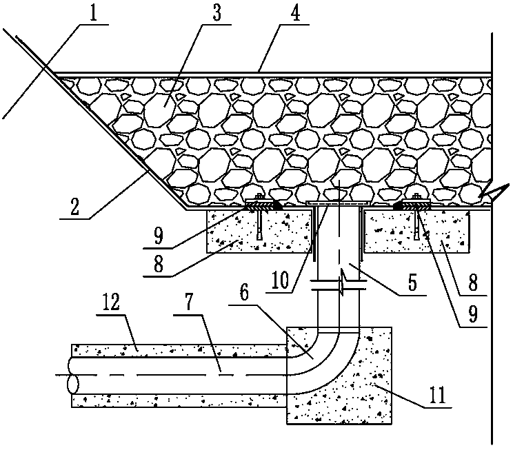
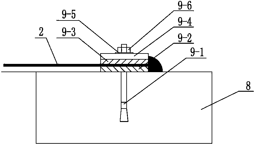
[0024] Such as figure 2 As shown, the present embodiment takes a valley-type landfill as an example. It forms a basin-shaped landfill reservoir area by building a garbage dam 1 at the entrance of the valley. HDPE anti-seepage film), on the top of the anti-seepage layer 2, the leachate drainage layer 3 and the filter geotextile 4 are laid in sequence from bottom to top, and the bottom of the landfill reservoir area is vertically arranged and the leachate drainage A short plastic pipe 5 connected to the layer 3. The upper end of the short plastic pipe has a flange and is welded to the anti-seepage layer 2 laid at the bottom of the reservoir area. The lower end is connected to the straight pipe 7 through the 90-degree elbow 6. The other end extends out of the garbage dam 1 and is connected to the external sewage treatment system; the number and elevation of the straight pipes 7 passing through the dam can be flexibly set according to the actual situation of the landfill, and wil...


PUM


Abstract

The invention relates to a ground leakage type water tight guiding and removing structure of a refuse landfill and a construction method thereof, which ensure whole integrity and water tight effectiveness of the ground leakage type water tight guiding bar structure of the refuse landfill. The technical scheme includes that the ground leakage type water tight guiding and removing structure of the refuse landfill is provided with a basin waste land filling area formed by building a waste dam. Water tight layers are paved at the bottom and surfaces of side slopes of the filling area. A leachate guiding and removing layer and filtration geotextile are sequentially paved at the position above the water tight layer from bottom to top. The ground leakage type water tight guiding and removing structure of the refuse landfill and the construction method of the guiding and removing structure are characterized in that a short plastic pipe communicated with the percolate guiding and removing layer is vertically distributed at the bottom of the waste land filling area. A flange is arranged at the upper end of the short plastic pipe which is connected with the water tight layer paved at the bottom of the filling area in welding mode. The lower end of the short plastic pipe is connected with a dam penetrating straight pipe penetrating through the bottom of the waste dam through a 90-degree elbow. The ground leakage type water tight guiding and removing structure of the refuse landfill and the construction method of the guiding and removing structure are applicable to waste land filling projects of city life.

Description

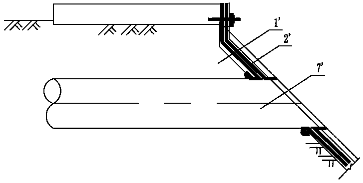
technical field [0001] The invention relates to a leakage-type anti-seepage and drainage structure and a construction method for landfill of garbage, which are mainly applicable to landfill projects of urban domestic garbage. Background technique [0002] For valley-type landfills, a garbage dam 1' is generally built at the entrance of the valley to form a basin-shaped landfill reservoir area. An anti-seepage layer 2' is laid on the bottom of the reservoir area and the slope of the valley, and a seepage layer is set above the anti-seepage layer 2'. The liquid drainage layer is used to collect the leachate produced by rainfall infiltration and self-decomposition of garbage during the landfill process. The leachate is introduced into the sewage treatment system through the guide pipe 7' for treatment. During the guide pipe 7', it needs to pass through the garbage dam body. The traditional method adopts the direct dam penetration process, that is, the guide pipe 7' follows the ...

Claims


Application Information

Patent Timeline
Patent Type & Authority Patents(China)
IPC IPC(8): E03F1/00E03F3/02E02D27/32E02D31/00
Inventor 陈亮魏俊陶如钧叶盛华徐玲娥
Owner POWERCHINA HUADONG ENG COPORATION LTD
Learn More