Eureka AIR delivers breakthrough ideas for toughest innovation challenges, trusted by R&D personnel around the world.

Rotating mechanism and excavating machine

A technology of slewing mechanism and roadheading machine, which is applied in the direction of slitting machinery, driving device, mining equipment, etc. It can solve the problems of uncoordinated roadheading machines, large torque changes, inconvenient installation and maintenance, etc., and achieve small layout space and activity space , The rotation torque is stable, and the effect of easy disassembly and maintenance

Active Publication Date: 2014-06-18
益阳市科技成果转化服务中心 +1
View PDF8 Cites 0 Cited by
  • Summary
  • Abstract
  • Description
  • Claims
  • Application Information

AI Technical Summary

Problems solved by technology

The rotary torque of the push-pull type on both sides of the hydraulic cylinder is closely related to the rotation angle. Therefore, the torque changes greatly during the rotary process; in addition, the use of the hydraulic cylinder push-pull rotary method has great limitations on the space layout of the roadheader, resulting in the rotation of the rotary cylinder. It is difficult to arrange the fuel tanks and consoles on both sides
[0004] Chinese patent document (application number is 200810054738.0, publication number is 101251011) discloses a rack hydraulic cylinder type rotary device, which uses the rack hydraulic cylinder to push the gear mounted on the rotary table to drive the rotary table to rotate at a certain angle. The slewing torque has nothing to do with the rotation angle, but this solution requires a large horizontal layout space for the roadheader, which is likely to cause the slewing cylinder to protrude laterally from the body of the roadheader, making the roadheader uncoordinated; Rotation requires a lot of space, which is not conducive to the use of small and medium-sized roadheaders, and it is also inconvenient to install and maintain

Method used


Image

  • Rotating mechanism and excavating machine
  • Rotating mechanism and excavating machine
  • Rotating mechanism and excavating machine

Examples


Embodiment Construction

[0025] In order to enable those skilled in the art to better understand the technical solution of the present invention, the present invention will be further described in detail below in conjunction with the accompanying drawings and specific embodiments. It should be pointed out that the description and sequence of specific structures in this section are only descriptions of specific embodiments, and should not be considered as limiting the protection scope of the present invention.

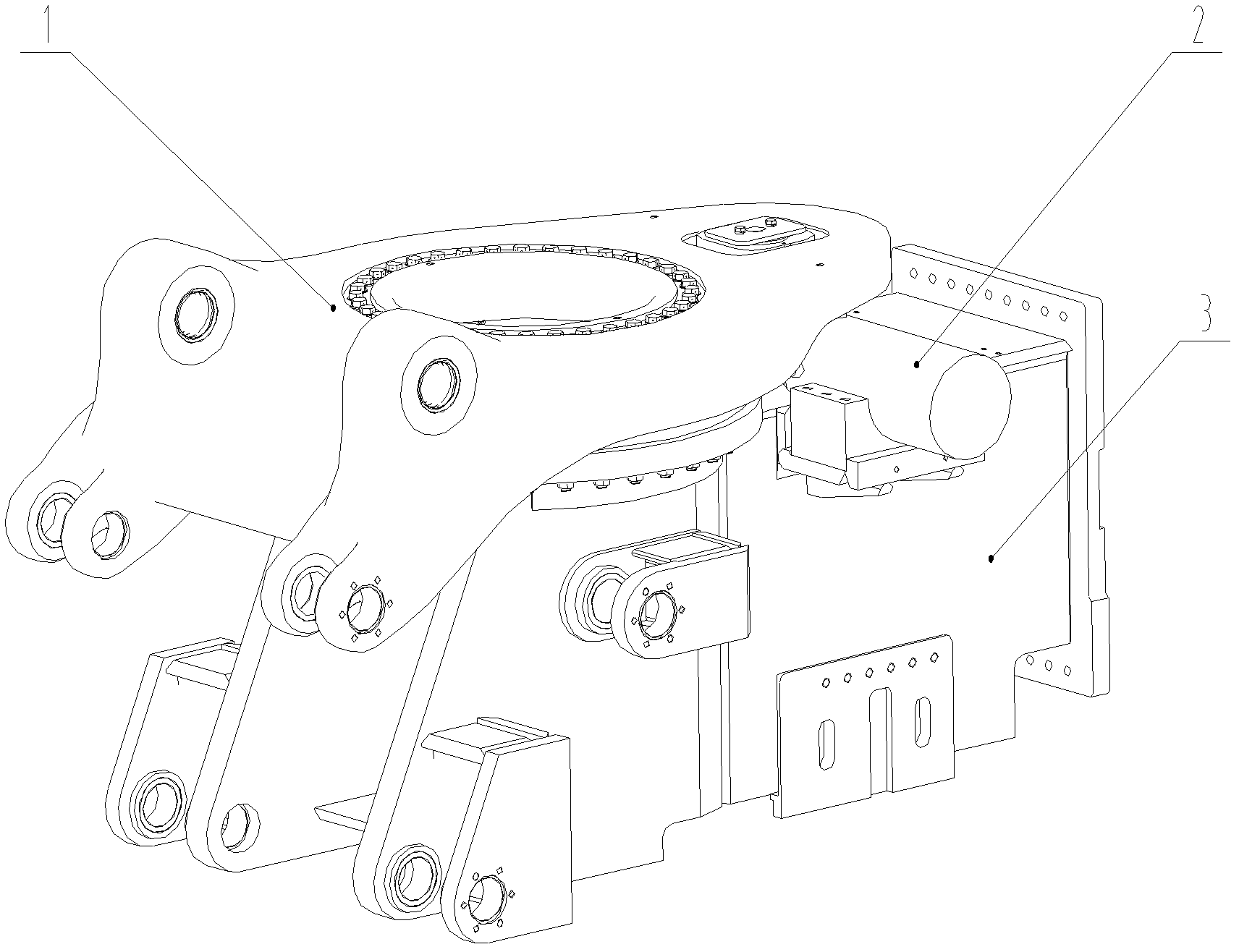
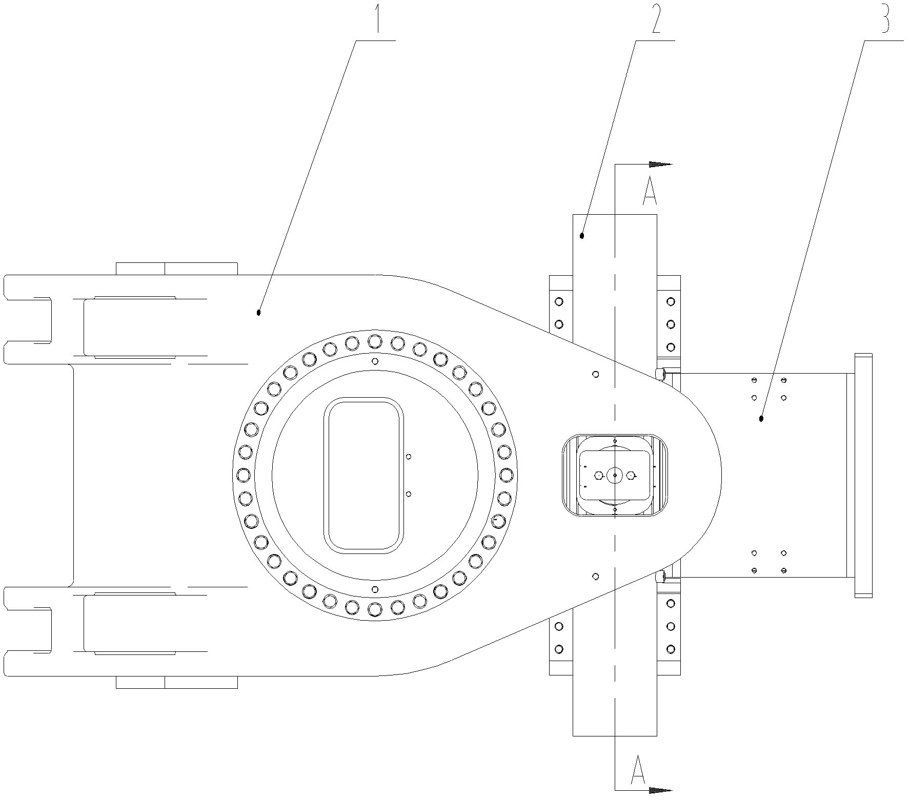
[0026] Please refer to Figure 2 to Figure 7 ,in, figure 2 It is a schematic structural diagram of a rotary mechanism provided by an embodiment of the present invention, image 3 for figure 2 top view of Figure 4 It is a schematic structural diagram of the turntable in the embodiment of the present invention, Figure 5 It is a schematic structural view of the oil cylinder in the embodiment of the present invention, Figure 6 It is a schematic structural diagram of the body in the embodi...


PUM


Abstract

Disclosed are a slewing mechanism and a tunneling machine. The slewing mechanism is used for driving the rotation of a cutting unit and comprises a body (3), and a rotary table (1) and a drive mechanism used for driving the rotation of the rotary table (1) are disposed on the body (3), wherein the drive mechanism is in a fixed configuration relative to the body (3), and comprises a drive part connected to the rotary table (1) and moving rectilinearly, the drive mechanism being able to convert the rectilinear movement of the drive part moving rectilinearly into the rotary movement of the rotary table (1). The slewing mechanism provided in the embodiments of the present invention uses an oil cylinder (2) with double cylinder bodies (21) as the drive mechanism, wherein, when a piston rod (22) of the oil cylinder (2) extends forwards and retracts backwards, the rotary table (1) is driven in rotation. Since the distance between the piston rod (22) and a rotary shaft of the rotary table (1) remains unchanged, the gyroscopic moment remains stable. Moreover, since the oil cylinder (2) has a transverse arrangement, only a relatively small size is required to be able to drive the rotary table (1) in rotation, and, during operation, the oil cylinder (2) does not follow the rotation of the rotary table (1), the piston rod (22) merely moving between the two cylinder bodies (21).

Description

technical field [0001] The invention relates to the technical field of engineering machinery, in particular to a slewing mechanism. The present invention also relates to a boring machine with the above-mentioned slewing mechanism. Background technique [0002] With the rapid development of economic construction, the coal industry continues to develop in the direction of mechanization and automation, and comprehensive mechanized mining equipment is more and more widely used in coal production under various geological conditions. In the operation of mechanized mining, the roadheader is one of the main mining equipment, and the excavation of the roadway is realized through the rotary cutting of the cutting part. [0003] At present, the rotary mode of the rotary table connected with the cutting part mainly adopts the push-pull type on both sides of the hydraulic cylinder and the rack hydraulic cylinder type. The principle diagram of the push-pull type on both sides of the hyd...

Claims


Application Information

Patent Timeline
Patent Type & Authority Patents(China)
IPC IPC(8): E21C31/10
CPCE21D9/1013E21D9/1086
Inventor 史成建支建燊胡建华
Owner 益阳市科技成果转化服务中心
Why Eureka
Eureka Blog
Learn More