
Turbocharger and working method thereof

A turbocharger and working method technology, applied in the direction of machines/engines, engine components, mechanical equipment, etc., can solve the problems of airflow hitting the back of the turbine blade or the concave surface of the blade, increasing the flow loss of the airflow, and reducing the thermal efficiency of the turbocharger, etc. , to achieve the effect of changing the cross-sectional area of ​​the nozzle, expanding the area of ​​the nozzle, and facilitating smooth passage

Inactive Publication Date: 2014-12-03
CHANGZHOU XINRUI AUTO PARTS MFG
View PDF9 Cites 0 Cited by
  • Summary
  • Abstract
  • Description
  • Claims
  • Application Information

AI Technical Summary

Problems solved by technology

But its disadvantage is: once the car runs at high speed, it will definitely cause the supercharger to overspeed.
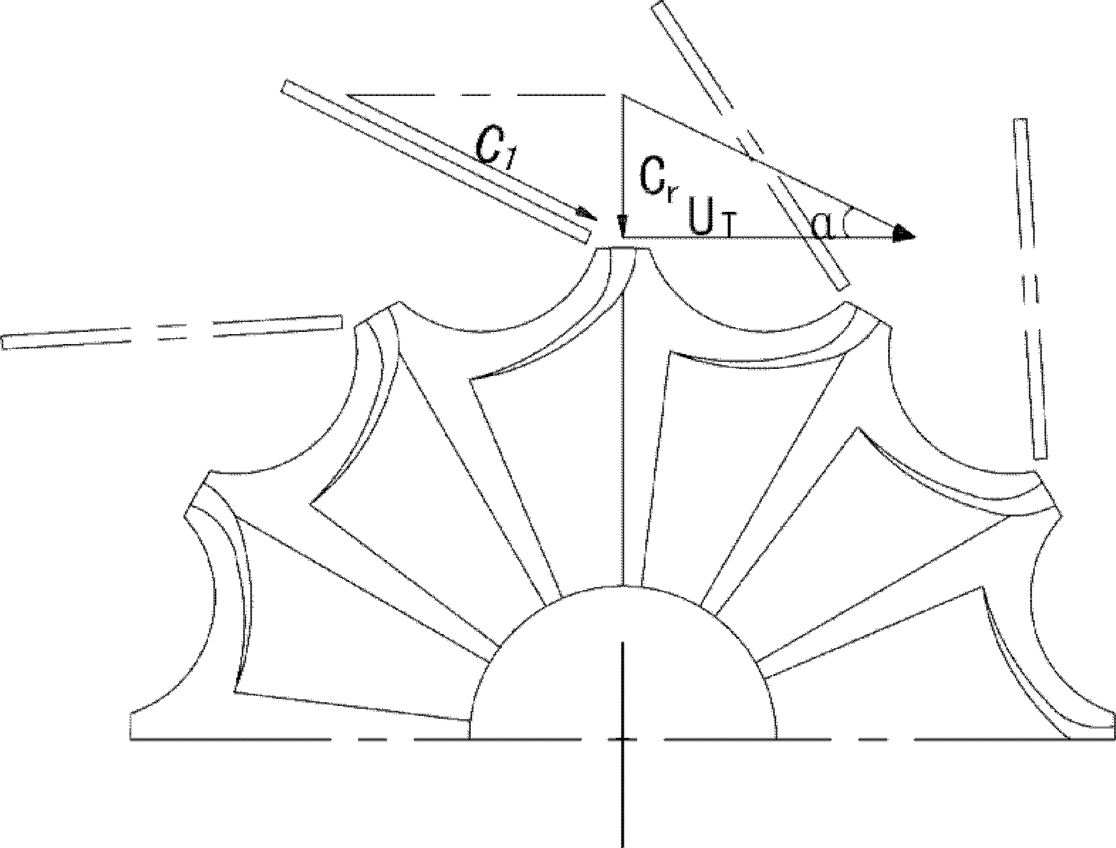
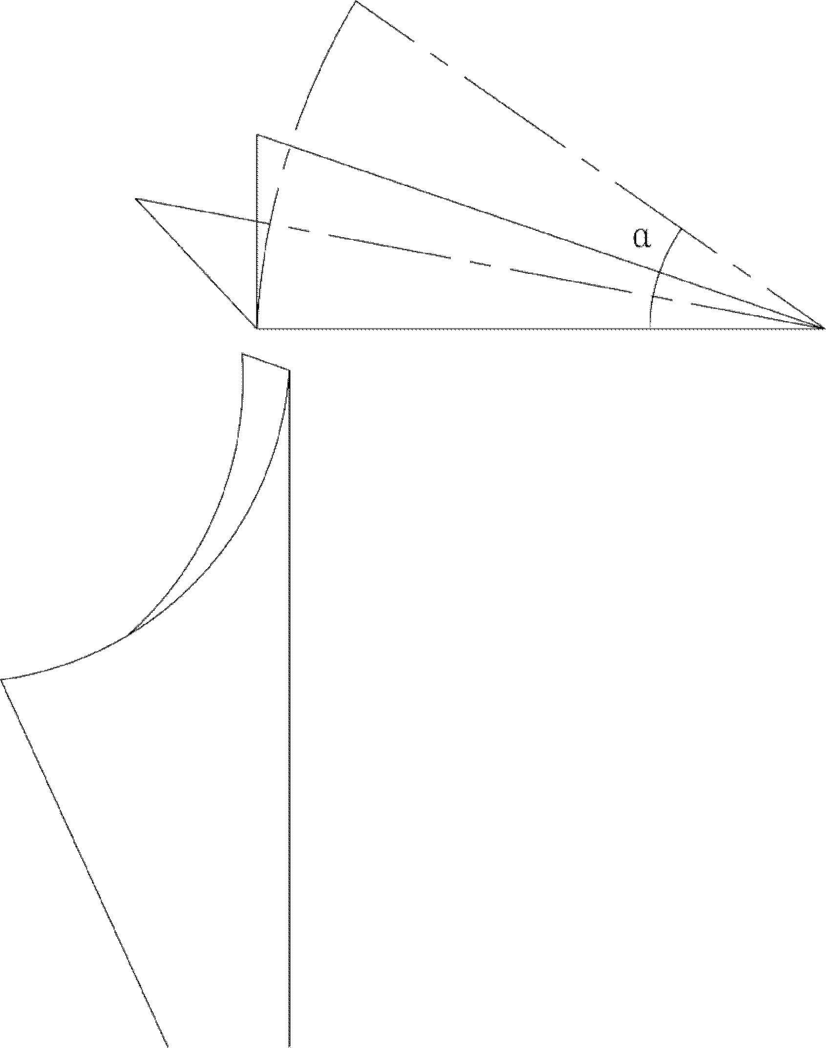
The disadvantage is that when the nozzle angle is too large (starting state) or too small (full negative state), the airflow will hit the back of the turbine blade or the concave surface of the blade (see image 3 ), so that the thermal efficiency of the turbocharger decreases when it works in low and high conditions
Because the airflow angles of the two energy channels are different, it will cause the airflow behind the nozzle to be turbulent and increase the flow loss of the airflow

Method used


Image

  • Turbocharger and working method thereof
  • Turbocharger and working method thereof
  • Turbocharger and working method thereof

Examples


Embodiment Construction

[0027] See Figure 4-8 The turbocharger of the present embodiment includes: a volute 1 arranged in the turbine casing, a volute fixed in the volute 1 and set on the outer periphery of the turbine impeller 10 for automatically controlling the nozzle cut-off according to the working conditions of the engine. area of ​​the nozzle ring assembly.

[0028] The nozzle ring assembly includes: a nozzle ring 4, a plurality of long nozzle blades 2 symmetrically distributed on the outer surface of the nozzle ring 4, and a pair of adjacent long nozzle blades arranged on the nozzle ring 4. The chute 11 between the nozzle blades 2, the movable short blade 3 arranged in the chute 11 and suitable for moving back and forth in a straight line along the nozzle airflow direction, the linkage ring 5 concentrically arranged on the inner surface of the nozzle ring 4, The chute holes 51 corresponding to the chute 11 distributed on the linkage ring 5, the three arc-shaped guide grooves 52 distributed ...


PUM


Abstract

The invention relates to a turbocharger and a working method thereof. The turbocharger comprises a volute arranged in a turbine casing body and a jet nozzle ring assembly which is fixed in the volute and sleeve on the periphery of an impeller of a turbine; the jet nozzle ring assembly comprises a jet nozzle ring, a plurality of long jet-nozzle blades distributed on the outer side face of the jet nozzle ring, a chute arranged between every two adjacent long jet-nozzle blades, short movable blades arranged in the chutes, linked rings concentrically arranged at the inner side surface of the jet nozzle ring, chute holes which are distributed on the linked rings and correspond to the corresponding chutes, a plurality of arc-shaped guide grooves which are distributed on the linked rings and are arranged concentrically to the linked rings, and a straight bolt arranged on the inner side surface of the jet nozzle ring; and a crank in transmission connection with a driving mechanism is arranged on an intermediate shell of the turbine and is connected with a pin hole in the linked rings through a crank shifting fork so as to drive the linked rings to rotate along a center and make the short movable blades displace in a linear reciprocating manner along a jet-nozzle airflow direction, and thus, the cross section of a jet nozzle is further controlled.

Description

technical field [0001] The invention relates to the technical field of turbochargers, in particular to a turbocharger with a variable nozzle outlet area and a working method thereof. Background technique [0002] The traditional turbocharger can only work in a small working range no matter in design or use, that is, it works in the high-efficiency zone. Some product design points are set at 90% of full load. When the engine is working in a low-load area, the supercharger must be in a low-efficiency working area. Therefore, this type of product is only suitable for steady-state and long-term full-load working conditions, such as turbochargers for marine and power generation. Some product design points are set at 50-70% of the working area. The purpose is to improve the high-efficiency performance at part load, and at the same time, the rotor is designed to be miniaturized to reduce the moment of inertia to improve the starting performance of the engine and the acceleration ...

Claims


Application Information

Patent Timeline
Patent Type & Authority Patents(China)
IPC IPC(8): F01D17/16
Inventor 杜向峰
Owner CHANGZHOU XINRUI AUTO PARTS MFG
Learn More