
Variable air valve lift mechanism of internal combustion engine

A technology of valve lift and valve mechanism, which is applied to internal combustion piston engines, combustion engines, machines/engines, etc., can solve the problem that the valve lift cannot be accurately controlled, the plunger rotation angle is not easy to accurately determine, and the exact moment of the oil level cannot be quickly determined. Good determination and other issues, to achieve the effect of improving power and fuel economy, facilitating miniaturization, and simple structure

Inactive Publication Date: 2012-03-21
SHANGHAI JIAO TONG UNIV
View PDF11 Cites 17 Cited by
  • Summary
  • Abstract
  • Description
  • Claims
  • Application Information

AI Technical Summary

Problems solved by technology

However, the exact moment at which the plunger seals against the oil surface is not well determined
In addition, because the angle of plunger rotation is not easy to be accurately determined, the valve lift cannot be precisely controlled.

Method used


Image

  • Variable air valve lift mechanism of internal combustion engine
  • Variable air valve lift mechanism of internal combustion engine
  • Variable air valve lift mechanism of internal combustion engine

Examples


Embodiment Construction

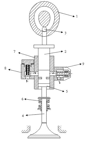
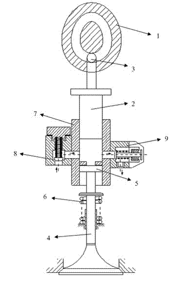
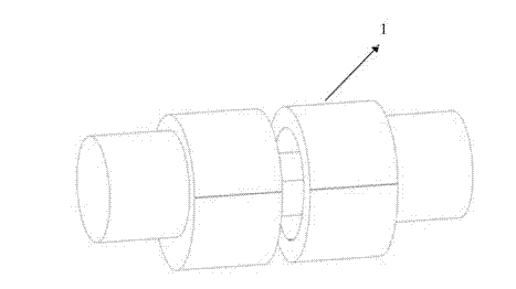
[0028] Such as figure 1 , figure 2 and Figure 4 As shown, the internal combustion engine variable valve lift mechanism provided in this embodiment includes a driving mechanism, a plunger pin 3, a hydraulic mechanism, a control valve and a valve mechanism, wherein the driving mechanism is connected with the hydraulic mechanism through the plunger pin 3, and the hydraulic mechanism The mechanism is connected with the valve mechanism, and the control valve is arranged on the hydraulic mechanism. The driving mechanism includes a grooved cam 1, which is connected to the hydraulic mechanism through a plunger pin 3; the hydraulic mechanism includes a hydraulic plunger 2 and a hydraulic cylinder 7, wherein the hydraulic plunger 2 is movably installed in the hydraulic cylinder 7 and is closely attached to the hydraulic cylinder One end of the plunger pin 3 is connected with the groove cam 1, and the other end of the plunger pin 3 is connected with the hydraulic plunger 2; the groov...


PUM


Abstract

The invention discloses a variable air valve lift mechanism of an internal combustion engine, which comprises a driving mechanism, a plunger pin, a hydraulic mechanism, a control valve and an air valve mechanism, wherein the driving mechanism is connected with the hydraulic mechanism through the plunger pin, the hydraulic mechanism is connected with the air valve mechanism, and the control valve is arranged on the hydraulic mechanism. According to the invention, as the hydraulic driving is adopted, the air valve lift continuously changes, so that the continuous change of the air incoming quantity of an engine can be adjusted, and further, the power performance and fuel economy of the engine can be improved. In the invention, the electrical control technology of the engine is combined, so that the opening and closing time of an electromagnetic valve can be accurately controlled, and further, the opening and closing time of the air valve and the air valve lift of can be accurately controlled. Simultaneously, the variable air valve lift mechanism disclosed by the invention has a relatively simple structure, so that the miniaturization of the engine is facilitated.

Description

technical field [0001] The invention relates to the technical field of internal combustion engines, in particular to a variable valve lift mechanism for internal combustion engines. technical background [0002] In order to meet the requirements of environmental protection and sustainable development of human beings, energy saving and emission reduction are the development goals of today's automobile engines. The variable valve lift technology changes the charge of the mixed gas entering the cylinder by adjusting the valve lift to improve the power and fuel economy of the engine. The ideal valve lift law should be adjusted in time according to the operating conditions of the engine, with sufficient flexibility. When the engine is running at low speed, the airflow speed is slow and the flow inertia is small, and the valve lift will cause the fresh air in the cylinder to flow back; when the engine is running at high speed, the airflow speed is fast and the flow inertia is la...

Claims


Application Information

Patent Timeline
IPC IPC(8): F01L13/00F01L1/12F02D13/02
CPCY02T10/18Y02T10/12
Inventor 徐敏邓康耀桂勇
Owner SHANGHAI JIAO TONG UNIV
Learn More