Self-locking device of transmission control mechanism

A technology of self-locking device and operating mechanism, which is applied in the direction of mechanical control device, transmission device control, instrument, etc., which can solve the problem of affecting the feel and comfort of the driver's gear shifting, adverse effects of gear shifting operation, and easy wear and damage of components and other issues, to improve the feel and comfort, protect components, and reduce friction

Inactive Publication Date: 2012-03-21
BEIQI FOTON MOTOR CO LTD
View PDF2 Cites 17 Cited by
  • Summary
  • Abstract
  • Description
  • Claims
  • Application Information

AI Technical Summary

Problems solved by technology

[0009] The technical problem to be solved by the present invention is that the self-locking steel ball, the self-locking spring and the housing generate a relatively large sliding friction force during the shift operation, which makes the parts prone to wear and damage, and affects the driver's shifting gear. The feel and comfort of the gear will have an adverse effect on the shifting operation

Method used


Image

  • Self-locking device of transmission control mechanism
  • Self-locking device of transmission control mechanism
  • Self-locking device of transmission control mechanism

Examples


Embodiment Construction

[0024] A specific embodiment of the present invention will be described in detail below in conjunction with the accompanying drawings. It should be understood that the specific embodiments described here are only used to illustrate and explain the present invention, and are not intended to limit the present invention.

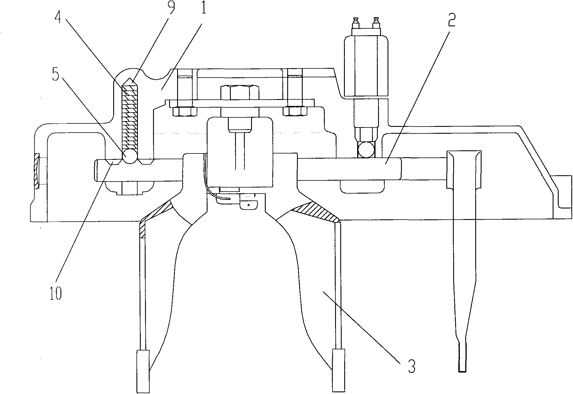
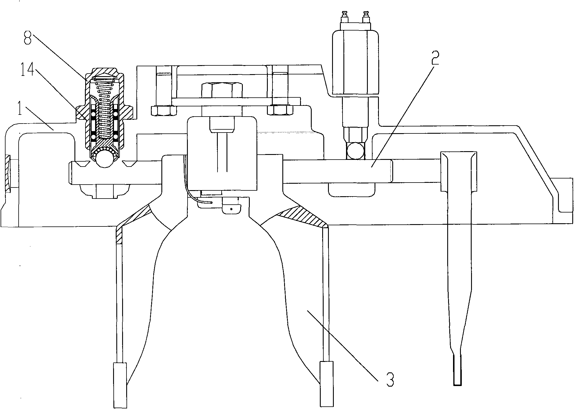
[0025] Such as figure 2 with image 3 As shown, the self-locking device of the transmission operating mechanism provided by a specific embodiment of the present invention, the self-locking device includes a housing 8, a shift fork shaft 2, a self-locking spring 4 and a self-locking steel ball 5. The housing 8 has a cavity 9, the self-locking spring 4 is accommodated in the cavity 9, the shift fork shaft 2 has a plurality of grooves 10, and the self-locking steel ball 5 passes through the self-locking fork shaft. The lock spring 4 is press-fitted in the groove 10, wherein the self-locking device also includes a spring bracket 6 and a bearing 7 located in the ...


PUM


Abstract

The invention relates to a self-locking device of a transmission control mechanism. The self-locking device comprises a shell (8), a gear-shifting fork shaft (2), a self-locking spring (4) and self-locking steel balls (5), wherein the shell (8) is provided with a cavity (9), the self-locking spring (4) is accommodated in the cavity (9), a plurality of grooves (10) are formed on the gear-shifting fork shaft (2), and the self-locking steel balls (5) are arranged in the grooves (10) in a press-fit manner through the self-locking spring (4), the self-locking device further comprises a spring bracket (6) and a bearing (7) in the cavity (9), the self-locking spring (4) is arranged on the upper part (61) of the spring bracket, the self-locking steel balls (5) are arranged at the lower part (62) of the spring bracket, and the bearing (7) is arranged between the spring bracket (6) and the shell (8). The self-locking device can be used for converting sliding friction among the self-locking steel balls (5), the self-locking spring (4) and the shell (8) into rolling friction, so that the friction force is reduced, the parts of the self-locking device are protected, and the hand feel and the comfortableness for gear shifting are improved.

Description

technical field [0001] The invention relates to an automobile transmission operating mechanism, and more particularly, relates to a self-locking device of an automobile transmission operating mechanism. Background technique [0002] The function of the automobile transmission control mechanism is that according to the driving conditions of the car, the driver can drive the shift fork shaft, shift block and shift fork to move at any time by operating the joystick, and change the transmission to or from a certain gear to achieve The basic action of gear selection and shifting realizes the function of shifting gears. [0003] In order to ensure that the transmission can work accurately, safely and reliably under any circumstances, safety devices are installed on the transmission operating mechanism, including: [0004] (1) Self-locking device, the self-locking device is composed of self-locking steel ball and self-locking spring, its function is to ensure that the shift is in ...

Claims


Application Information

Patent Timeline
Patent Type & Authority Applications(China)
IPC IPC(8): F16H59/02F16H63/32F16H63/34
CPCF16H63/38
Inventor 程方涛王艳辉黄斌赵淑英
Owner BEIQI FOTON MOTOR CO LTD
Why Eureka
Try Eureka