
Customized vehicle shielding system

a vehicle shielding and custom technology, applied in the direction of shields, vehicle bodies, advertising, etc., can solve the problem that no prior art document provides an automated vehicle shielding system, and achieve the effect of simple operation

Active Publication Date: 2016-03-15
KHOURY JOHNNY MICHEL
View PDF21 Cites 6 Cited by
  • Summary
  • Abstract
  • Description
  • Claims
  • Application Information

AI Technical Summary

Benefits of technology

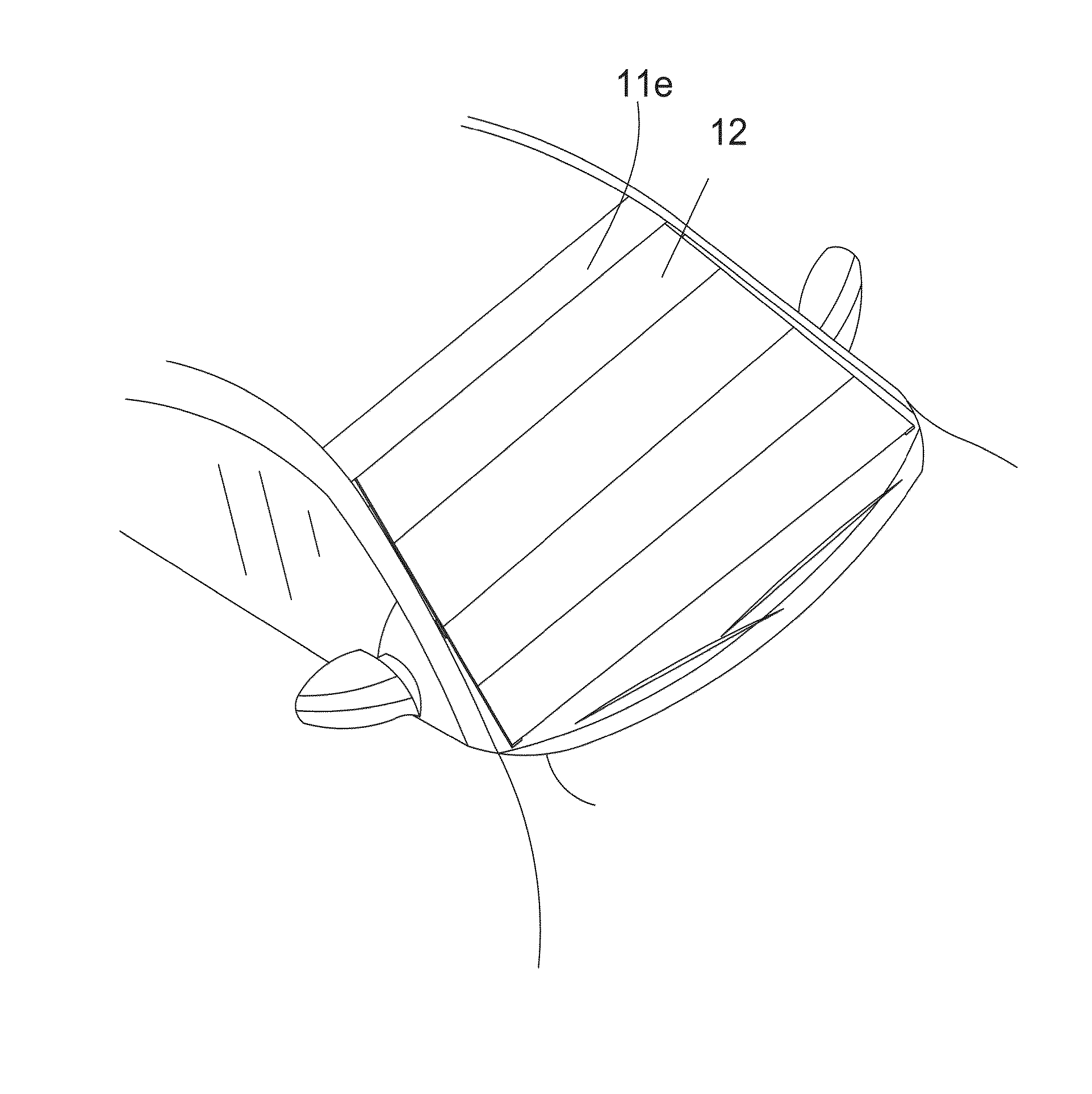
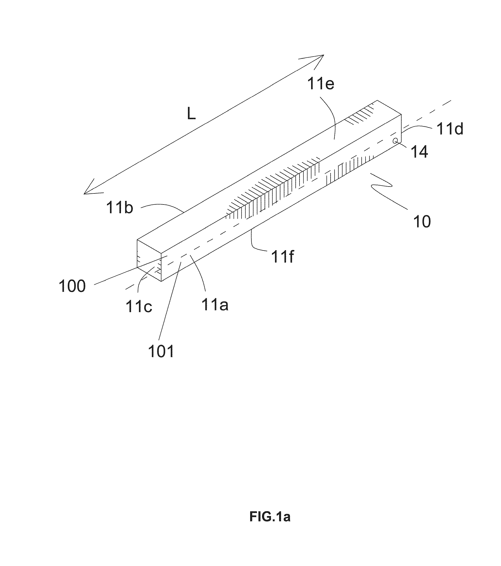
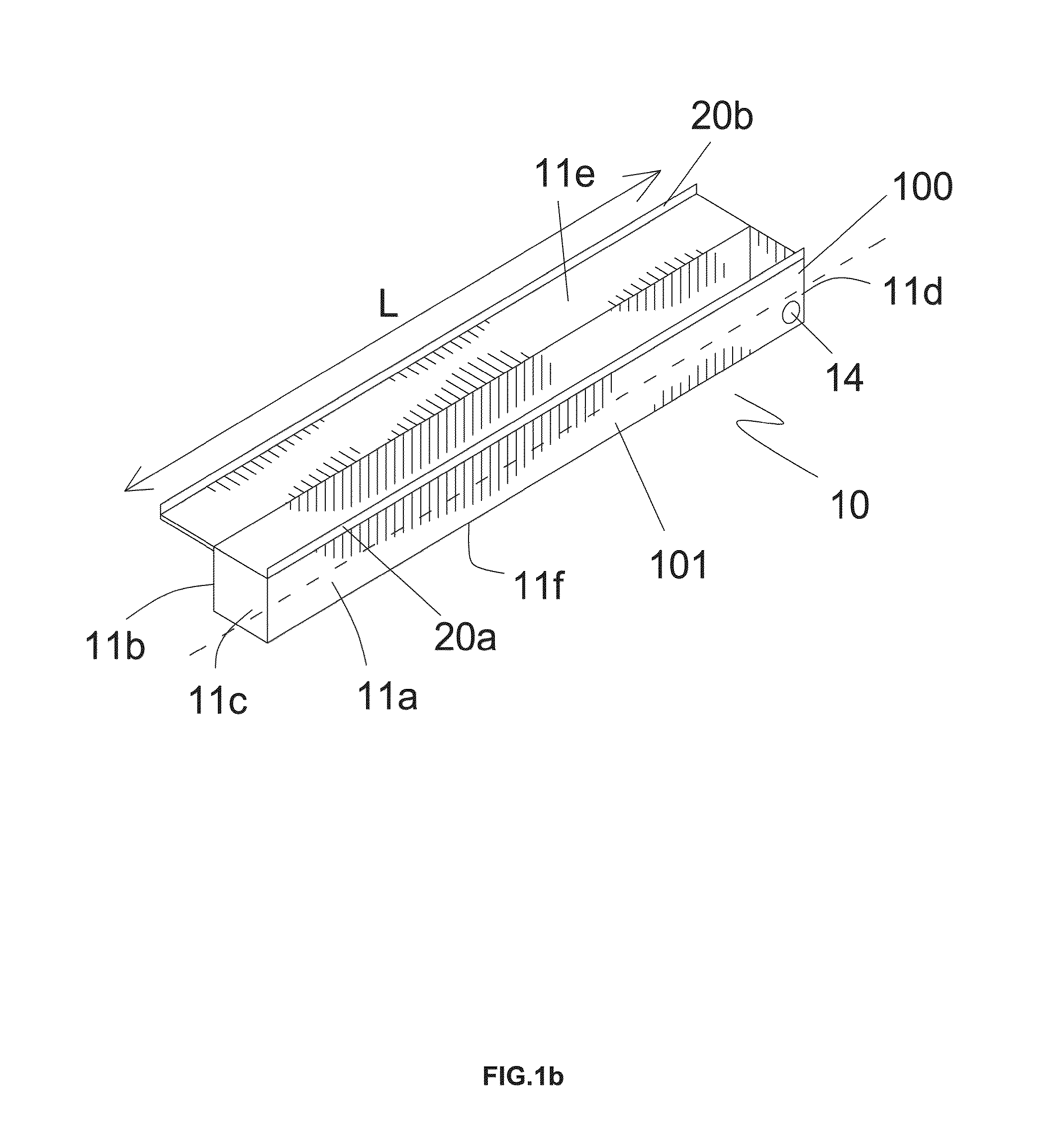
The present invention provides an automated vehicle shielding system that is simple to operate, customizable to adapt to all vehicle shapes and sizes, and does not affect the aerodynamic characteristics of the vehicles. Additionally, the system protects the shielded part of the vehicle from external conditions, such as rain, snow, and wind. The system includes a housing with a plurality of walls, at least one of which is adapted to move between an open position and a closed position, a shielding material that alternates between an extended and retracted position, a mechanism for alternating the shielding material between the extended and retracted positions, a draining means, and means for providing self-cleaning capability. Preferably, the at least one movable member is adapted to avoid causing damage to the vehicle's body.

Problems solved by technology

None of the prior art documents provide an automated vehicle shielding system that could be built-in or added-on while protecting the vehicle from certain external conditions without affecting aesthetics of the vehicle, but maintaining or improving the vehicle's aerodynamics, and that is easy to operate.
Furthermore, none of the prior art documents provide an automated vehicle shielding system that can be installed on all vehicle sizes.

Method used


Image

  • Customized vehicle shielding system
  • Customized vehicle shielding system
  • Customized vehicle shielding system

Examples


example 1

End of Example 1

Example 2

[0074]Throughout this example, reference will be made to FIGS. 5a-5c with continued reference to FIGS. 1-3.

[0075]In another example, said at least one movable member comprises at least one telescoping member 16, wherein such telescoping member alternates between an extended position and a retracted position, wherein said extended position is defined as the position in which the shielding material is covering the desired part of the vehicle's body, and wherein said retracted position is defined as the position in which the at least one telescoping member 16 and the shielding material 12 are enclosed in the housing 10.

[0076]Said at least one actuator 130 along with the coupling mechanism are adapted to translate the said telescoping member along at least a part of the housing length L.

[0077]The at least one actuator 130 along with the coupling mechanism are adapted to translate the at least one telescoping member 16 towards and away from the housing 10, wherei...

example 2

End of Example 2

Example 3

[0078]Throughput this example, reference is made to FIGS. 6a-6c, with continued reference to FIGS. 1-3.

[0079]Yet in another example, said at least one movable member comprises at least one disc or ring-shaped member 17, wherein such member 17 is connected to said at least one actuator 130. Said at least one actuator 130 along with the coupling mechanism are adapted to roll said at least one disc or ring-shaped member 17 along the portion of the vehicle to be shielded.

[0080]In case there is a plurality of members 17, a flexible member 19 is used to connect between said members 17.

example 3

End of Example 3

End of Examples


PUM


Abstract

The present invention relates to a customized vehicle shielding system used for shielding at least a part of a vehicle, wherein such system essentially comprises a housing with a plurality of walls, a shielding material adapted to alternate between an extended position and a retracted position, a mechanism for extending and retracting the shielding material, and draining means. A user can operate the system of the present invention remotely. The vehicle shielding system of the present invention has self-cleaning capability.

Description

BACKGROUND OF THE INVENTION[0001]1. Field of the Invention[0002]The present invention relates to an automated vehicle shielding system for the protection of vehicles from certain external conditions.[0003]2. Description of the Related Art[0004]The use of shielding and shading systems and devices is well known in the prior art. For instance, numerous patents and patent applications disclose various shading devices and systems used to provide shading and protection for vehicles' windshields.[0005]As an example, the U.S. Pat. No. 8,419,107 provides a retractable vehicle shade including a hollow central box, a front sliding panel, and a rear sliding panel. The hollow central box is mounted on a rooftop of the vehicle. The front sliding panel is slidingly fitted into the box through a slot at the front end and configured to cover at least front glass pane. The rear sliding panel is slidingly fitted into the box through the slot at the rear end and configured to cover at least rear glass ...

Claims


Application Information

Patent Timeline
Patent Type & Authority Patents(United States)
IPC IPC(8): B60J11/04G09F21/04F41H7/02F41H5/06B60J9/00B62D35/00
CPCB60J9/00B62D35/00G09F21/048B60J11/04F41H5/06F41H7/02B60J11/08F41H5/013G09F21/0485
Inventor KHOURY, JOHNNY, MICHEL
Owner KHOURY JOHNNY MICHEL
Learn More