High-pressure automatic gas drainage device

A drainer and automatic technology, which is applied in gas/liquid distribution and storage, pipeline system, mechanical equipment, etc., can solve the problems of difficult installation, bloated, enlarged equipment, etc., to reduce production costs, reduce labor intensity, and reduce infrastructure The effect of investment

Inactive Publication Date: 2012-03-21
NANTONG SHENDONG METALLURGICAL MACHINERY
View PDF4 Cites 3 Cited by
  • Summary
  • Abstract
  • Description
  • Claims
  • Application Information

AI Technical Summary

Problems solved by technology

However, when the pressure of the gas pipeline is ≥0.1MPa, the traditional gas drain has the following technical problems and design defects: due to the high pressure of the gas pipeline, the height of the effective water seal that the drain needs to form to overcome the gas pressure will increase accordingly, which will inevitably cause The gas drainer equipment is huge and bloated, which not only increases the production cost of the equipment, but also makes it difficult to install the equipment when the user site is limited
This requires the on-site operators to have a high level of operation. At the same time, it is necessary to frequently check and repair the supporting valves on the dry drain. Once the valve is damaged or the worker makes a wrong operation during the drainage operation, the gas cannot be cut off in time and effectively. will be unimaginable
[0004] 2. The user needs to manually operate the drainage frequently and regularly, which greatly increases the labor intensity of the workers
[0005] Therefore, the traditional high-pressure gas drain cannot realize automatic, continuous and safe drainage, and it is necessary to improve the high-pressure drain

Method used


Image

  • High-pressure automatic gas drainage device
  • High-pressure automatic gas drainage device

Examples


Embodiment Construction

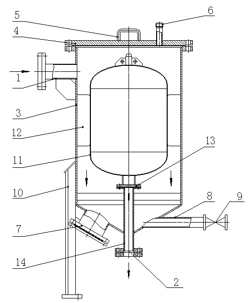
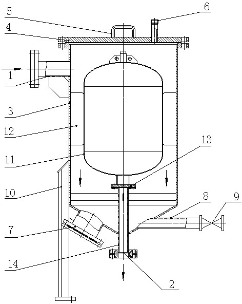
[0016] like figure 1 As shown, the high-pressure automatic gas drainer of the present invention includes a housing 3 with a water inlet 1 and a water outlet 2, the water inlet 1 is located on one side of the housing 3, the water outlet 2 is located at the bottom of the housing 3, and the housing The top of the body 3 is provided with a top cover 4, the top cover 4 is provided with a handle 5 and an exhaust port 6, one side of the bottom of the housing 3 is provided with a hand hole 7, and the other side of the bottom of the housing 3 is connected by a sewage pipe 8 There is a sewage outlet 9, the outside of the shell 3 is provided with a leg 10, the shell 3 is provided with a buoy 11, the two sides of the buoy 11 are provided with a buoy positioning device 12, and the buoy positioning device 12 is fixed on the side wall of the shell 3, The bottom of the buoy 11 is provided with a sealing device 13, the sealing device 13 is a sealing ring, and a drainage pipe 14 is provided dir...


PUM


Abstract

The invention discloses a high-pressure automatic gas drainage device. The high-pressure automatic gas drainage device comprises a shell, wherein the shell is provided with a water inlet and a water outlet; the water inlet is formed on one side of the shell; the water outlet is formed at the bottom of the shell; a top cover is arranged at the top end of the shell; a handle is arranged on the top cover and an exhausting opening is formed in the top cover; a hand hole is formed on one side at the bottom of the shell; the other side at the bottom of the shell is connected with a sewage draining opening through a sewage draining pipe; and a supporting foot is formed out of the shell. The high-pressure automatic gas drainage device is characterized in that: a buoyancy pontoon is arranged in the shell; buoyancy pontoon positioning devices are arranged on the two sides of the buoyancy pontoon; the buoyancy pontoon positioning devices are fixed on the side wall of the shell; a sealing device is arranged at the bottom of the buoyancy pontoon; a drainage pipe is arranged under the buoyancy pontoon; part of the drainage pipe is positioned on the lower part of the shell and part of the drainage pipe penetrates out of the shell; and a water outlet is formed at the end of the drainage pipe. The high-pressure automatic gas drainage device has the advantages that: the structure is simple, the work is safe, the automation degree is high, the labor intensity is lightened, the production cost of equipment is reduced, and the high-pressure automatic gas drainage device is suitable for various working conditions.

Description

technical field [0001] The invention relates to a gas drainer, in particular to a high-pressure automatic gas drainer. Background technique [0002] The gas drainer is mainly used for the removal of condensed water in the gas pipeline. The working principle of the gas drainer is: by injecting water into the drainer, the effective water seal height formed in the drainer is used to overcome the gas pressure to achieve the purpose of removing gas condensate. However, when the pressure of the gas pipeline is ≥0.1MPa, the traditional gas drain has the following technical problems and design defects: due to the high pressure of the gas pipeline, the height of the effective water seal that the drain needs to form to overcome the gas pressure will increase accordingly, which will inevitably cause The gas drainer equipment is huge and bloated, which not only increases the production cost of the equipment, but also makes it difficult to install the equipment when the user's site is l...

Claims


Application Information

Patent Timeline
Patent Type & Authority Applications(China)
IPC IPC(8): F17D3/14
Inventor 余红辉陈永新沈冬玲
Owner NANTONG SHENDONG METALLURGICAL MACHINERY
Why Eureka
Try Eureka