Asymmetrical-loading integral circular interpolation method of numerical control system

A circular interpolation, numerical control system technology, applied in general control system, control/regulation system, program control and other directions, can solve the problems of increasing machine tool cost, high hardware requirements, complex algorithm and so on

Active Publication Date: 2012-03-21
XUZHOU JIULONG ELECTRONICS IND CO LTD
View PDF6 Cites 3 Cited by
  • Summary
  • Abstract
  • Description
  • Claims
  • Application Information

AI Technical Summary

Problems solved by technology

However, the algorithm is complex and requires high h

Method used


Image

  • Asymmetrical-loading integral circular interpolation method of numerical control system
  • Asymmetrical-loading integral circular interpolation method of numerical control system
  • Asymmetrical-loading integral circular interpolation method of numerical control system

Examples


Embodiment 1

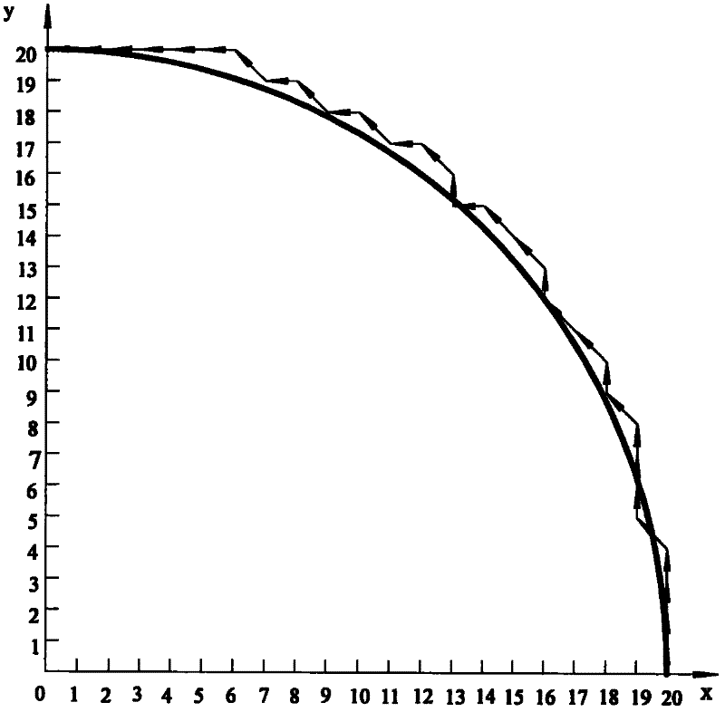
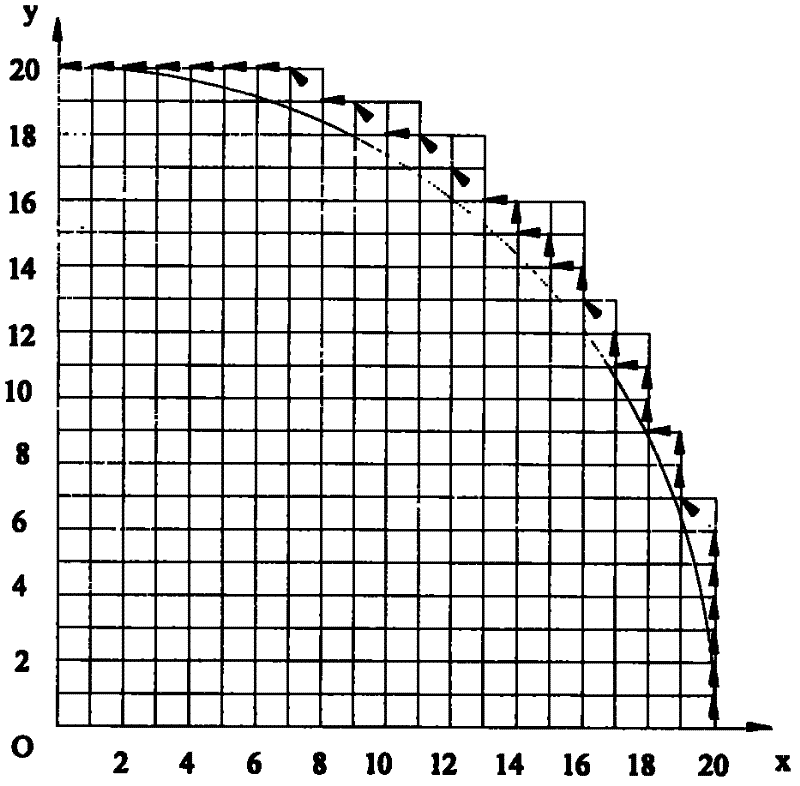
[0034] Interpolate the arc AB with the asymmetric loading integral arc interpolation method, the starting point coordinate of the arc AB is A(20,0), and the end point coordinate is B(0,20), then the proportional coefficient q=max( x 0 ,y 0 , x e ,y e )=max(20, 0, 0, 20)=20, its interpolation trajectory is as Figure 6 As shown, the x-axis pulse distribution waveform is as Figure 7 As shown, the y-axis pulse distribution waveform is as Figure 8 shown.

[0035] The interpolation of the arc AB can be obtained by comparison, the interpolation times of the traditional integral circular interpolation method is 51 times; the interpolation times of the asymmetric loading integral circular interpolation method is 31 times. The number of imputations is reduced by 39.216%.

[0036] image 3 and Figure 6 By comparison, it can be calculated that the maximum interpolation error of traditional integral circular interpolation is The maximum interpolation error of the asymmetric ...

Embodiment 2

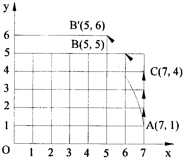
[0043] Use the asymmetric loading integral circular interpolation method to interpolate circular arc AB. The starting point coordinates of circular arc AB are A(7,1), and the end point coordinates are B(5,5), so the number of pulses is q= max(x 0 ,y 0 , x e ,y e )=max(7,1,5,5)=7, its interpolation trajectory is as Figure 12 shown. The interpolation of the arc AB can be concluded by comparison that the interpolation times of the traditional integral circular interpolation method is 6 times; the interpolation times of the asymmetric loading integral circular interpolation method is 4 times, and the interpolation times A reduction of 33.333%. and figure 1 In comparison, after the interpolation ends, the actual tool position just falls on the end point coordinate B(5, 5). The x-axis pulse distribution waveform is as Figure 13 shown, with Figure 10 In comparison, the maximum pulse interval is reduced from 5 to 2. The y-axis pulse distribution waveform is as Figure 14...


PUM


Abstract

The invention discloses an asymmetrical-loading integral circular interpolation method of a numerical control system, belonging to the technical field of numerical-control processing of the numerical control system. The values of integral accumulators are increased by an asymmetrical loading method, that is to say, an integral accumulator fed in the direction of an axis where the starting point of a circular arc is located is assigned with an initial value which is the smallest integer greater than or equal to two thirds of the maximal increment in the direction, while an integral accumulatorfed in the direction of other axis is assigned with an initial value which is the biggest integer less than or equal to a half of the maximal increment in the direction. The method provided in the invention performs asymmetrical loading on the x-axis and the y-axis, so that the machining accuracy of workpieces is improved by more than one time while the production rate is not reduced; after the asymmetrical loading, the difficulty of an interpolation algorithm is not increased, but the times of interpolation are obviously reduced; the distribution of pulses is even; and the speed of interpolation is increased; however, the cost of the machine is not increased. Moreover, the method is adaptive to various open-loop control systems, so that the application range of the economical numerical control machines is expanded.

Description

technical field [0001] The invention relates to an asymmetric loading integral arc interpolation method of a numerical control system, which belongs to the technical field of digital control processing of a numerical control system. Background technique [0002] The traditional integral circular interpolation method cannot be used in the numerical control system with higher requirements. The goal of the reference pulse interpolation method is to reduce the system cost and computational complexity while meeting the performance requirements, so that the system can use cheap processors and simple small and medium-scale integrated circuits as much as possible, and reduce the cost of machine tools. However, it cannot be applied to systems with high requirements because: ①If the system is realized by hardware, although it can solve the problem of processing speed, it cannot perform very complicated interpolation calculations, which will affect the interpolation performance of the ...

Claims


Application Information

Patent Timeline
IPC IPC(8): G05B19/41
Inventor 范希营郭永环
Owner XUZHOU JIULONG ELECTRONICS IND CO LTD
Why Eureka
Try Eureka