Optical device for detecting and identifying damaged paper money by using photosensitive element

A technology of photosensitive elements and optical devices, which is applied in the authenticity inspection of banknotes, handling coins or valuable banknotes, instruments, etc., can solve the problems of high misidentification and omission resolution, difficult installation, high maintenance requirements, etc., and achieve photoelectric signal Obvious, low false positive rate, accurate detection effect

Inactive Publication Date: 2012-03-21
温州泓鼎商用机器有限公司
View PDF4 Cites 7 Cited by
  • Summary
  • Abstract
  • Description
  • Claims
  • Application Information

AI Technical Summary

Problems solved by technology

[0003] In order to overcome the problems of high misidentification and omission rate, high cost, high maintenance requirements and difficult installation in the traditional banknote detection mechanism in the prior art, the present invention provides an optical device that uses photosensitive elements to detect and identify damaged banknotes. The structure is simple, the cost is low, the requirements for mechanical installation are not high, and there is no contact with the banknotes, no need for frequent maintenance, it can accurately judge whether there are holes in the banknotes, whether there are stains, whether the banknotes are inclined when entering the sorting machine, whether there are adhesive strips and Precisely detect the position of the glue strip

Method used


Image

  • Optical device for detecting and identifying damaged paper money by using photosensitive element
  • Optical device for detecting and identifying damaged paper money by using photosensitive element
  • Optical device for detecting and identifying damaged paper money by using photosensitive element

Examples


Embodiment Construction

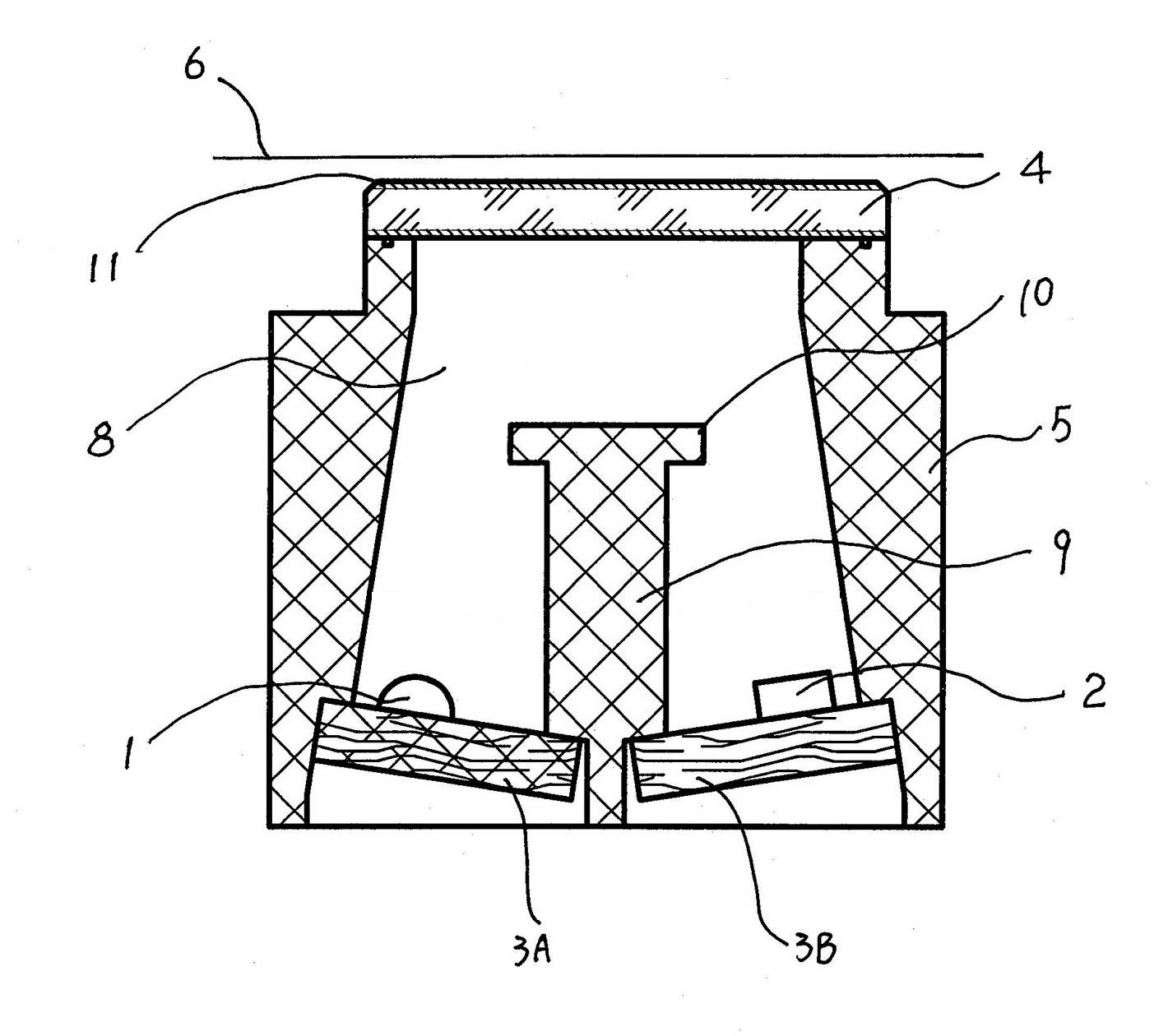
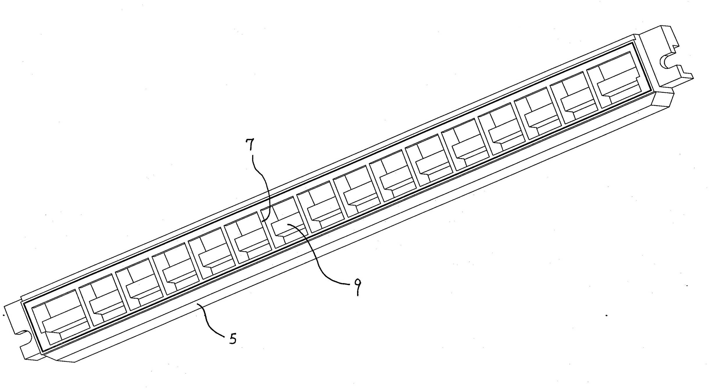
[0020] As shown in the figure, the present invention includes a light-emitting tube array 1, a receiving tube array 2, a light-emitting signal processing circuit board 3A, a receiving signal processing circuit board 3B, a light-transmitting plate 4 and a bracket 5, and the light-transmitting plate 4 is generally made of optical glass and fixed Installed at the position above the bracket 5, an anti-reflection film 11 corresponding to the wavelength of the emitted light is compounded on the light-transmitting plate 4. The design purpose of the anti-reflection film 11 is to enhance the transmittance of the emitted light and reduce the reflection of the light on the glass surface. Therefore, the proportion of the light reflected by the banknote surface in the light received by the receiving tube is increased. One side of the banknote to be identified passes through the surface of the light-transmitting plate 4 above the device, and the light-emitting signal processing circuit board...


PUM


Abstract

The invention relates to an optical device for detecting and identifying damaged paper money by using a photosensitive element. The optical device comprises a luminous tube array, a receiving tube array, a light transmission board and a bracket, wherein the light transmission board is fixedly arranged above the bracket; a luminous signal processing circuit board and a received signal processing circuit board are fixedly arranged at the inner bottom of the bracket; the inner part of the bracket is partitioned into relatively independent light detection cavities by partition walls; each light detection cavity is opposite to the luminous signal processing circuit board and the received signal processing circuit board; and the luminous tube array and the receiving tube array which are matched with each other in the light detection cavity are fixed on the luminous signal processing circuit board and the received signal processing circuit board respectively. By the optical device, the shortcomings of high error distinction rate and leakage rate, high cost, high maintenance requirement and high installation difficulty in the prior art are overcome; due to the specific design, whether various damages exist on paper money or not can be judged accurately; and the optical device has the advantages of low cost, simple structure and low mechanical installation requirement; furthermore, the optical device is not contacted with the paper money, so the optical device is not required to be maintained frequently.

Description

technical field [0001] The invention relates to banknote sorting financial equipment, in particular to an optical device in banknote sorting equipment that uses photosensitive elements to detect and identify damaged banknotes. Background technique [0002] Banknotes will inevitably be torn and damaged in the circulation of daily life and commercial activities. People often use adhesive strips to paste and repair them before continuing to use them. Therefore, in the sorting process of banknotes, it is of great practical significance to identify the adhesive strips attached to the banknotes. However, there has been no very effective method for detecting the adhesive strip on banknotes. The traditional detection method is to detect by measuring its thickness, that is, to judge whether the banknote has an adhesive strip by detecting the small increment of the banknote. But because some rubber strips are very thin, the thinnest of the most commonly used rubber strips is only 0.0...

Claims


Application Information

Patent Timeline
Patent Type & Authority Applications(China)
IPC IPC(8): G07D7/12G07D7/128G07D7/187G07D7/189
Inventor 吴建霖杨沧海宋白桦杨承然贾志峰
Owner 温州泓鼎商用机器有限公司
Why Eureka
Try Eureka