

Unreeling device in copper tube
A technology of internal wire laying and copper pipes, which is applied in the field of cables, can solve the problems of not being able to adapt well to new process requirements, the large footprint of the wire discharging device, and the reduction of the quality of coaxial cables, etc., to achieve a small footprint, High disk changing efficiency, maintaining shape and roundness
Active Publication Date: 2013-07-03
JIANGSU TRIGIANT TECH
View PDF5 Cites 0 Cited by
- Summary
- Abstract
- Description
- Claims
- Application Information
AI Technical Summary
Problems solved by technology
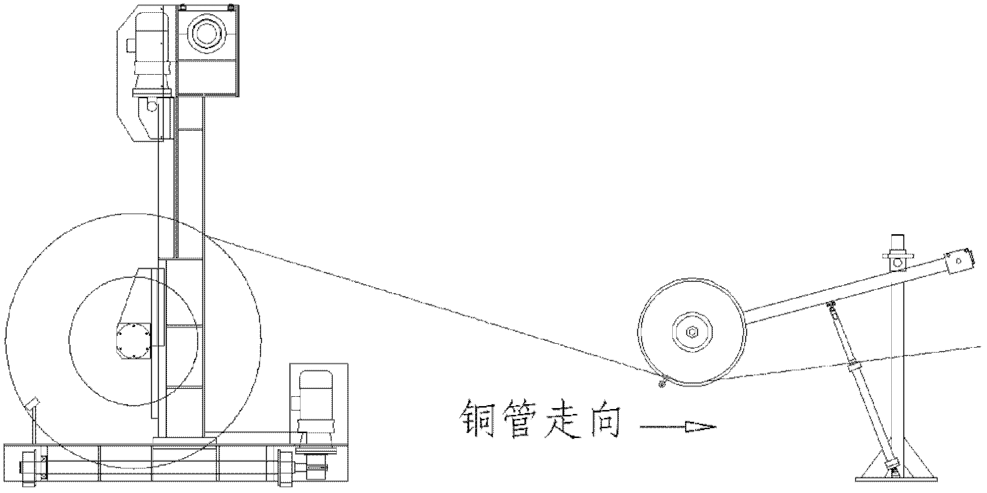
In actual use, such as figure 1 , the existing pay-off device has several disadvantages: one is that the entire pay-off device occupies a larger area; The increase of disk change time will affect the production efficiency; the third is that the cost of equipment is high, in order to ensure the uniformity of tension, it is necessary to use active pay-off racks, which work together with movable ground rails, position sensors, and tension dance wheels; four is , with the increasing shortage of copper resources and the rising international copper prices, the thickness of the existing copper tubes is getting thinner and thinner. Problems such as copper tube bending, flattening, scratching, and poor wiring are becoming more and more serious, which greatly reduces the quality of coaxial cables
[0003] To sum up, the existing copper tube pay-off device can no longer adapt to the new process requirements, and the production efficiency is low and the transportation cost is high, so there is still room for improvement
Method used
View moreImage
Smart ImageViewing Examples

Examples
Embodiment Construction
Login to View More PUM
| Property | Measurement | Unit |
|---|---|---|
| height | aaaaa | aaaaa |
Abstract
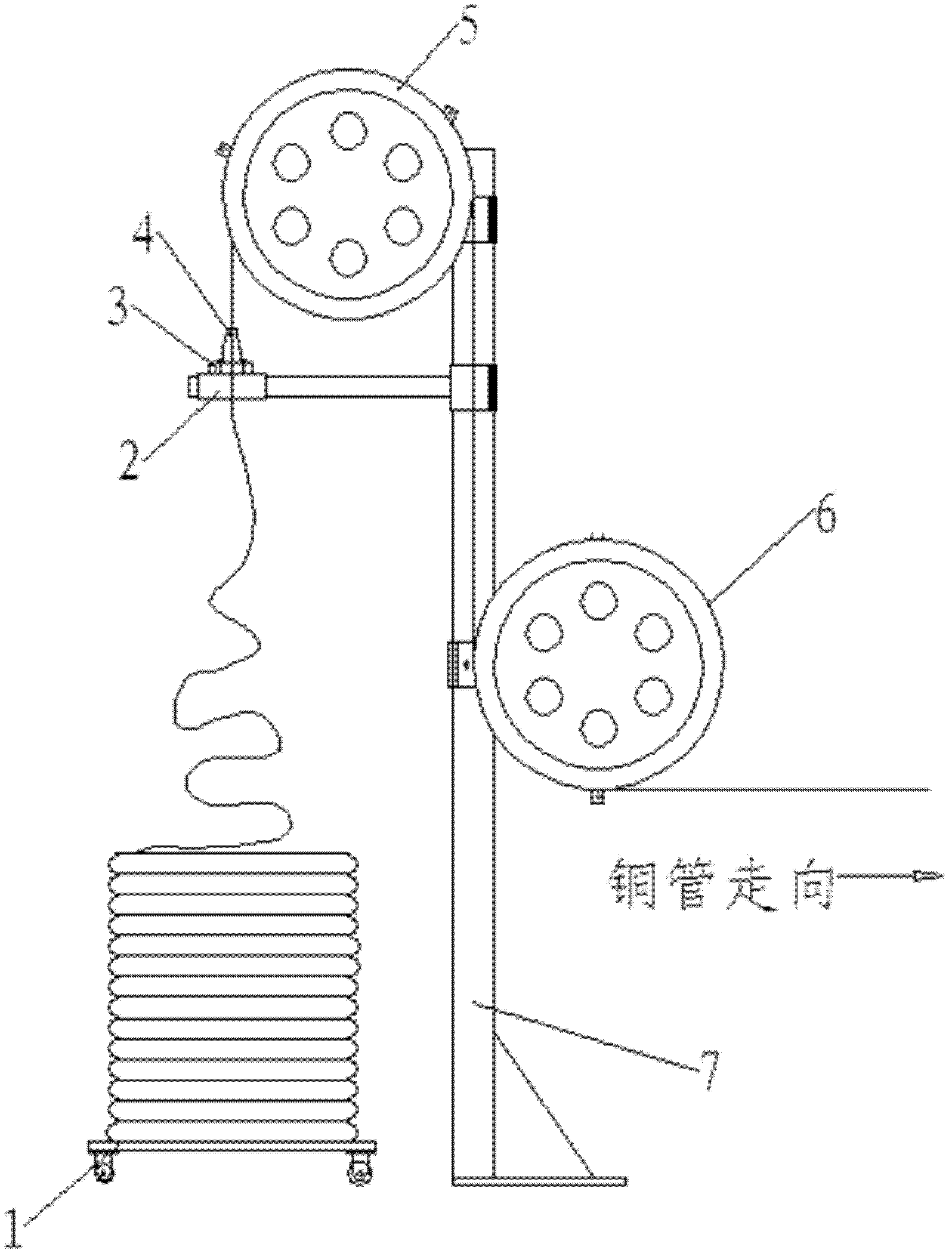
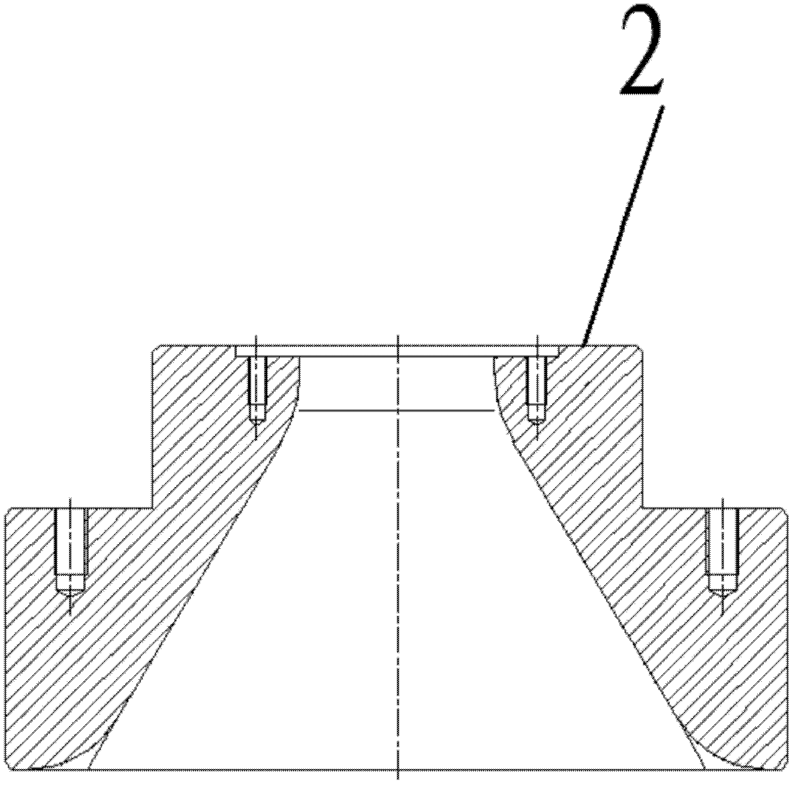
The utility model relates to an unreeling device in a copper tube, which comprises a bottom wheel supporting rack (1), a horn mould (2), a connecting plate (3), a wire passing mould (4), an upper guide wheel (5), a lower guide wheel (6) and a base (7). The connecting plate (3) is disposed between the horn mould (2) and the wire passing mould (4). A flange guide structure on the head in the coppertube is employed in the unreeling device, so that floor area is reduced, and two wire plates can be placed at the same time; and a connector can be made in advance, so that a break will not be causedin the process of replacing the wire plates, and continuous production is ensured, thereby improving working efficiency of the whole production line. The unreeling device is simple in manufacturing process, low in cost, high in production efficiency and more reliable in quality of product.
Description
technical field [0001] The invention relates to the field of cables, in particular to a copper tube internal pay-off device for coaxial cables. Background technique [0002] In the field of communication transmission, coaxial cable, as an important signal transmission medium, can be widely used in communication signal transmission fields such as base station feeders, communication equipment connecting lines and indoor distribution. The existing coaxial cable inner conductor pay-off device includes three parts: vertical gantry pay-off frame, position sensor and tension dancer. In actual use, such as figure 1 , the existing pay-off device has several shortcomings: first, the entire pay-off device occupies a large area; second, it is inconvenient to change the reel, that is, only one reel can be placed at a time. The increase in the time of changing the disk will affect the production efficiency. Third, the equipment cost is high. In order to ensure the uniformity of the tens...
Claims
Login to View More Application Information
Patent Timeline
 Patent Type & AuthorityPatents(China)
IPC IPC(8): H01B13/016
Inventor张爱军吴健真姚文讯冯玲芳
OwnerJIANGSU TRIGIANT TECH