High-voltage direct-current cable terminal using shielding cylinder

A high-voltage direct current, cable terminal technology, applied in the direction of the cable terminal, to achieve the effect of uniform field strength along the surface and increase the flashover voltage

Active Publication Date: 2012-03-21
STATE GRID ELECTRIC POWER RES INST
View PDF10 Cites 4 Cited by
  • Summary
  • Abstract
  • Description
  • Claims
  • Application Information

AI Technical Summary

Problems solved by technology

[0004] However, the existing patents have not been able to solve the problem of the influence of the internal electric field and the external electric field to make the field strength distribution of the composite sleeve or porcelain sleeve more uniform along the surface

Method used


Image

  • High-voltage direct-current cable terminal using shielding cylinder
  • High-voltage direct-current cable terminal using shielding cylinder

Examples


Embodiment Construction

[0013] The present invention will be further described in detail below in conjunction with the accompanying drawings and examples, but these examples should not be construed as limiting the present invention.

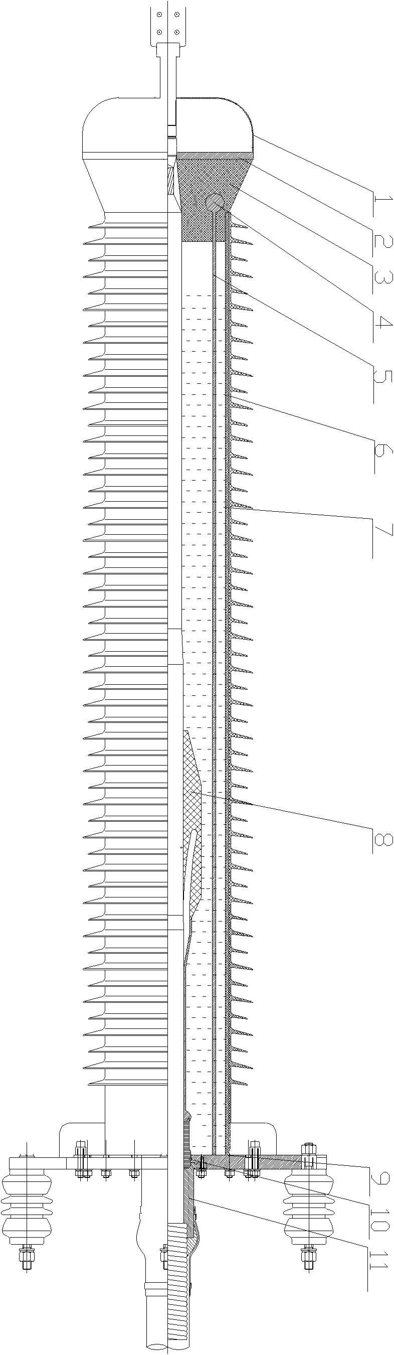
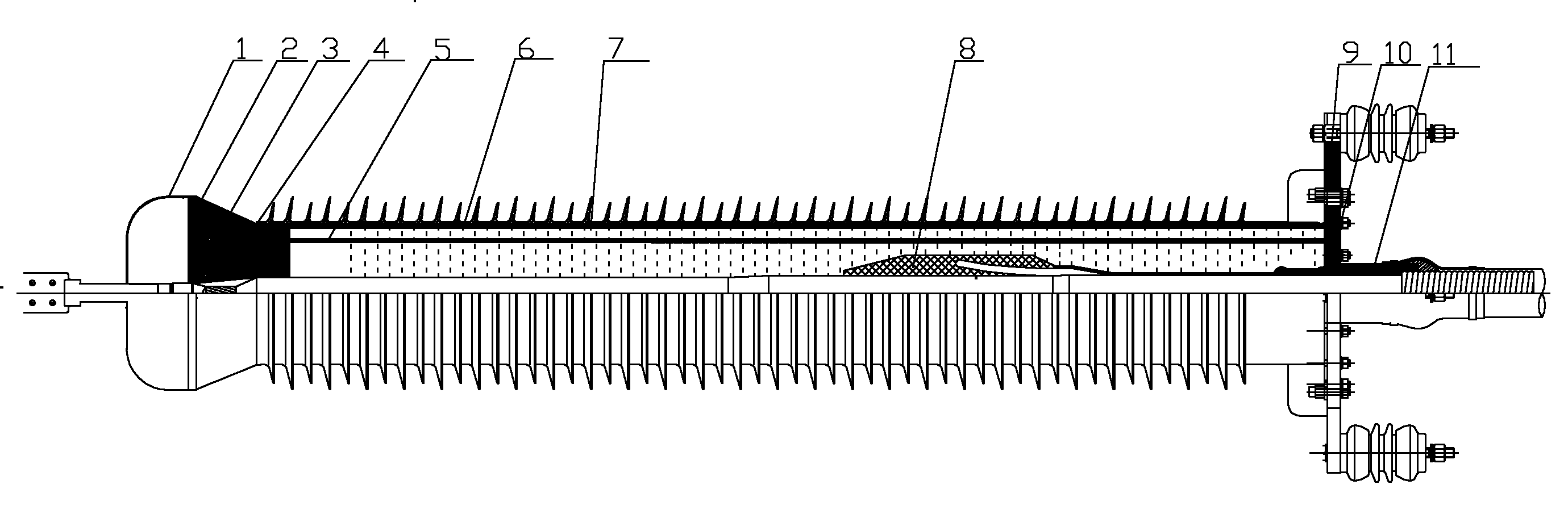
[0014] Description of reference symbols: 1 upper electrode, 2 upper flange, 3 epoxy parts, 4 shielding ring, 5 shielding cylinder, 6 epoxy composite sleeve (or porcelain sleeve), 7 insulating oil, 8 stress cone, 9 lower method Lan, 10 sealing ferrules, 11 tailpipes.

[0015] The embodiment of the present invention provides a high-voltage DC cable terminal with a shielding cylinder, including an upper electrode 1, an upper flange 2, an epoxy part 3, a shielding ring 4, a shielding cylinder 5, an epoxy composite sleeve (or porcelain sleeve ) 6. Insulating oil 7, stress cone 8, lower flange 9, sealing ring 10 and tailpipe 11.

[0016] On the cable at the high-voltage DC cable terminal, the upper electrode 1, the upper flange 2, the epoxy part 3, the stress cone 8, the sea...


PUM


Abstract

The invention relates to a high-voltage direct-current cable terminal comprising a shielding cylinder. The high-voltage direct-current cable terminal comprises: a top electrode, an upper flange, an epoxy composite sleeve, an insulating oil, a stress cone, a lower flange, a sealed ring and a tail tube. The high-voltage direct-current cable terminal is characterized in that: the terminal also comprises: an epoxy piece, a shielding ring and the shielding cylinder; the top electrode is arranged on an upper part of the upper flange; the epoxy piece is connected with the upper flange; the shielding ring is embedded in the epoxy piece; the epoxy piece is connected with the epoxy composite sleeve; the shielding ring is connected with shielding cylinder; the epoxy composite sleeve is filled with the insulating oil; the shielding cylinder is infiltrated in the insulating oil so as to connect with the lower flange; the lower flange and the cable are sealed by the sealed ring; the lower flange is connected with the tail tube and is well grounded. In the direct-current cable terminal of the invention, because of using the metal shielding cylinder, the shielding is formed between the internal and external electric fields, which reaches a purpose of uniform composite sleeve shed or porcelain sleeve shed surface field intensity. And a purpose of increasing a flashover voltage can be achieved too.

Description

technical field [0001] The invention relates to a high-voltage direct current cable terminal, in particular to a high-voltage direct current cable terminal using a shielding cylinder. Background technique [0002] At present, many literatures have pointed out that DC bushings will have wet flash at lower voltage than AC bushings. The reason is that DC bushings designed with AC bushings are more likely to form dry under wet conditions under the action of DC electric field. area, the dry area bears a larger voltage and is more likely to form a flashover. For the cable terminal with the same form of insulation principle as the bushing, it is currently designed for AC cables, and if the DC cable terminal follows the design of the AC cable terminal, it is also prone to wet flash. The reason is that the pollution of the cable terminal under the AC electric field is relatively light, while under the DC electric field, due to the constant electric field force, the particles and dus...

Claims


Application Information

Patent Timeline
Patent Type & Authority Applications(China)
IPC IPC(8): H02G15/04
Inventor 陈铮铮赵健康张丽闵红
Owner STATE GRID ELECTRIC POWER RES INST
Why Eureka
Try Eureka