LED (Light-emitting Diode) lamp with temperature-control protective circuit

A temperature control protection, LED lamp technology, applied in the direction of electric lamp circuit layout, electric light source, lighting device, etc., can solve the problems of unable to realize the lighting function, unable to meet the needs of use, and achieve the effect of reducing heat generation, reducing power, and avoiding burning

Inactive Publication Date: 2012-03-21
NANKER GUANGZHOU SEMICON MFG
View PDF6 Cites 13 Cited by
  • Summary
  • Abstract
  • Description
  • Claims
  • Application Information

AI Technical Summary

Problems solved by technology

However, in some occasions, even if the temperature is high, lighting is still required. At this time, if the lamp is turned off, the lighting function cannot be realized and cannot meet the needs of use.

Method used


Image

  • LED (Light-emitting Diode) lamp with temperature-control protective circuit
  • LED (Light-emitting Diode) lamp with temperature-control protective circuit
  • LED (Light-emitting Diode) lamp with temperature-control protective circuit

Examples


Embodiment 1

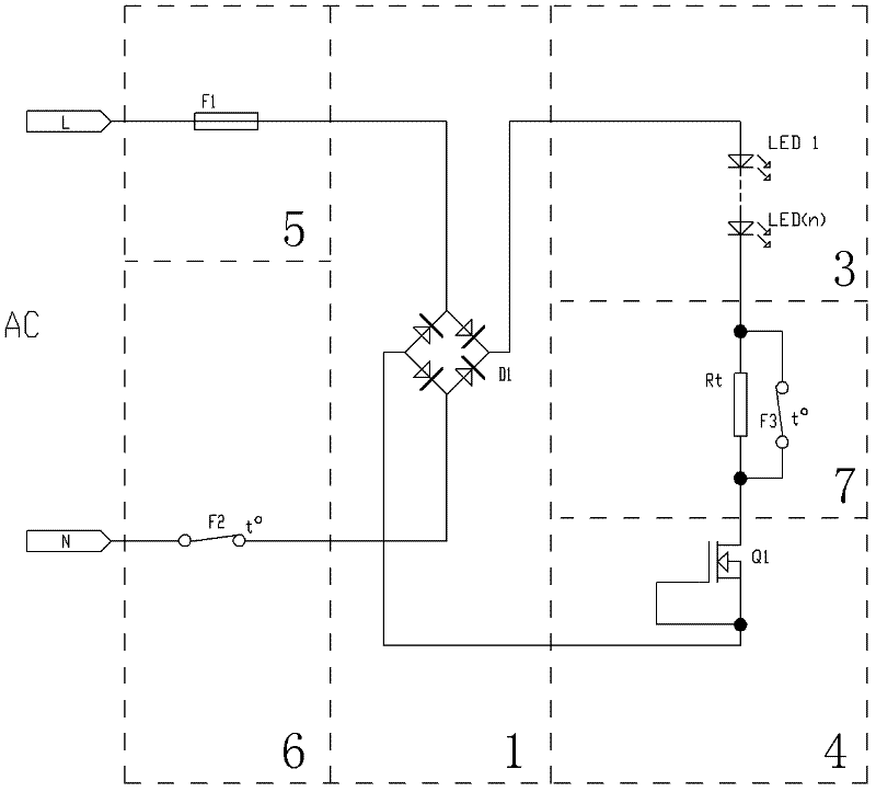
[0032] Such as figure 1 , Figure 5 , Figure 6 , Figure 9 , Figure 10As shown, the LED lamp with a temperature control protection circuit in this embodiment includes a power board 101 for supplying power to the LED light source and its temperature control protection circuit, a radiator 102 for dissipating heat for the LED light source, a waterproof and dustproof lampshade 103, Reflector 104, the temperature control protection circuit includes a rectifier circuit 1 for changing alternating current into direct current, an LED light source load 3, a constant current circuit 4 for stabilizing voltage and current for the LED light source load 3, and an overcurrent protection circuit 5 , the first temperature control switch circuit 6, the second temperature control switch circuit 7; the rectification circuit 1 adopts bridge rectification including a rectification bridge D1, of course other rectification methods can also be used for rectification, and the overcurrent protection...

Embodiment 2

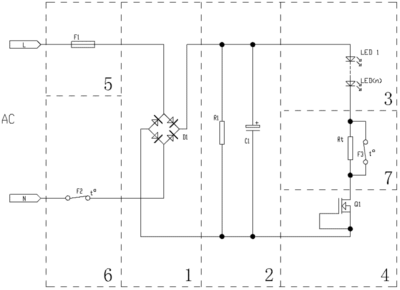
[0036] Such as figure 2 , Figure 5 , Figure 6 , Figure 9 , Figure 10 As shown, the difference between this embodiment and Embodiment 1 is that in this embodiment, the temperature control protection circuit also includes a filter circuit 2, and the filter circuit 2 is connected after the rectifier circuit 1. In this embodiment, The filter circuit 2 mentioned above includes a filter capacitor C1 and a discharge resistor R1. Of course, other filter circuits can also be used to provide a more stable current for the LED light source load 3. However, due to the addition of a filter capacitor, the power factor will be affected to a certain extent. influences.

[0037] The remaining features of this embodiment are the same as those of Embodiment 1.

Embodiment 3

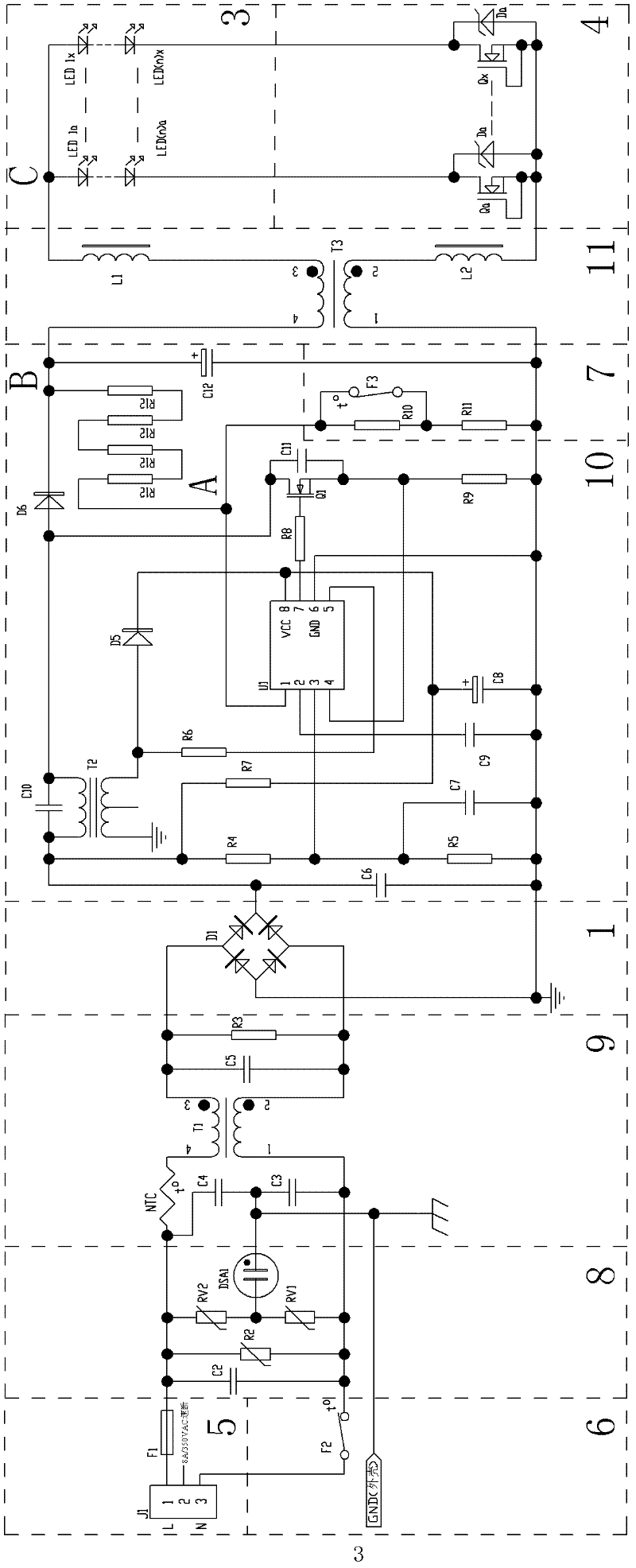
[0039] Such as image 3 , Figure 7 ~ Figure 10As shown, the LED lamp with a temperature control protection circuit in this embodiment includes a power board 101 for supplying power to the LED light source and its temperature control protection circuit, a radiator 102 for dissipating heat for the LED light source, a waterproof and dustproof lampshade 103, A reflector 104, an airtight power supply box 105 for protecting the power board 101 from water and dust, the temperature control protection circuit includes a rectifier circuit 1 that converts alternating current into direct current, an LED light source load 3, and a LED light source load 3 Constant current circuit 4 for voltage and current stabilization, overcurrent protection circuit 5, first temperature control switch circuit 6, second temperature control switch circuit 7, power supply lightning protection circuit 8, power supply EMC circuit 9, voltage stabilization and PFC circuit 10. Light source EMC circuit 11; the re...


PUM


Abstract

The invention discloses an LED (Light-emitting Diode) lamp with a temperature-control protective circuit. The LED lamp comprises a power supply board (101), the temperature-control protective circuit and a radiator (102); the temperature-control protective circuit comprises a rectifying circuit (1), an LED light source load (3), a constant-current circuit (4) and first and second temperature-control switch circuits (6, 7); the first temperature-control switch circuit (6) comprises a first normally-closed temperature-control switch (F2) which is arranged on the radiator (102); when the temperature of the radiator (102) is higher than a switch-off temperature of the first normally-closed temperature control switch (F2), the first normally-closed temperature-control switch (F2) is switched off to cut off the supply power of the LED light source load (3); the second temperature-control switch circuit (7) comprises a second normally-closed temperature-control switch (F3) which is installed on the power supply board (101) and a voltage-dividing resistor; when an environment temperature of the circuit is higher than the switch-off temperature of the second normally-closed temperature-control switch (F3), the second normally-closed temperature-control switch (F3) is switched off and the current passes through the voltage-dividing resistor, so that a power supply current of the LED light source load (3) is reduced; and the LED lamp can be applied to the LED illumination field.

Description

technical field [0001] The invention relates to an LED lamp with a temperature control protection circuit. Background technique [0002] At present, the application of LEDs is becoming more and more extensive, and LED lamps for daily indoor and outdoor lighting are also becoming more and more popular. The current LED lighting is more and more developing towards high power, and the high heat brought by high-power LEDs is an important factor that plagues the popularization of LEDs. If the LED works at high temperature for a long time, its service life will be greatly shortened, which will affect the display of its advantages, and even cause dead lights, resulting in the scrapping of the lamps. If the lamp can be automatically turned off when overheating, the above adverse consequences can be avoided. However, in some occasions, even if the temperature is high, lighting still needs to be carried out. If the light fixture is turned off at this time, the lighting function canno...

Claims


Application Information

Patent Timeline
Patent Type & Authority Applications(China)
IPC IPC(8): H05B37/02
Inventor 吴俊纬
Owner NANKER GUANGZHOU SEMICON MFG
Why Eureka
Try Eureka