
Support construction having increased structural dampening

A technology for load-bearing structures and load-bearing elements, applied in building components, building structures, bridges, etc., can solve problems such as technical difficulties, implementation and corrosion protection problems, and achieve the effect of easy maintenance.

Inactive Publication Date: 2015-03-18
VSL INT AG
View PDF6 Cites 0 Cited by
  • Summary
  • Abstract
  • Description
  • Claims
  • Application Information

AI Technical Summary

Problems solved by technology

Petersen writes that the solution he describes is technically difficult to implement and corrosion protection is particularly problematic

Method used


Image

  • Support construction having increased structural dampening
  • Support construction having increased structural dampening
  • Support construction having increased structural dampening

Examples


Embodiment Construction

[0074] In the following elaboration, the first involves Figure 1 to Figure 10 .

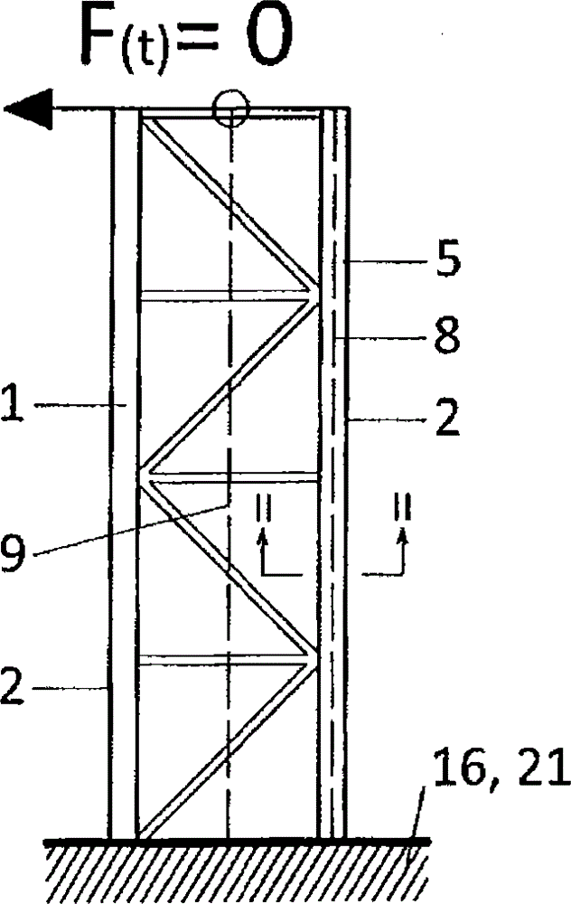
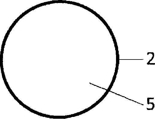
[0075] exist figure 1 The load-bearing structure 1 for absorbing the force F(t) acting at the upper end is shown in the undeformed state (F(t)=0). The load-bearing elements 2 of the load-bearing structure 1 consist of rods and beams. The cavity 5 is located in the carrier element 2 which is designed as a steel tube. The axis of the center of gravity of the support structure 1 is indicated with 9 and the axis of the center of gravity of the support element 2 is indicated with 8 . The foundation 16 serves as an abutment 21 for the load-bearing structure. figure 2 A section through carrier element 2 with cavity 5 is shown.

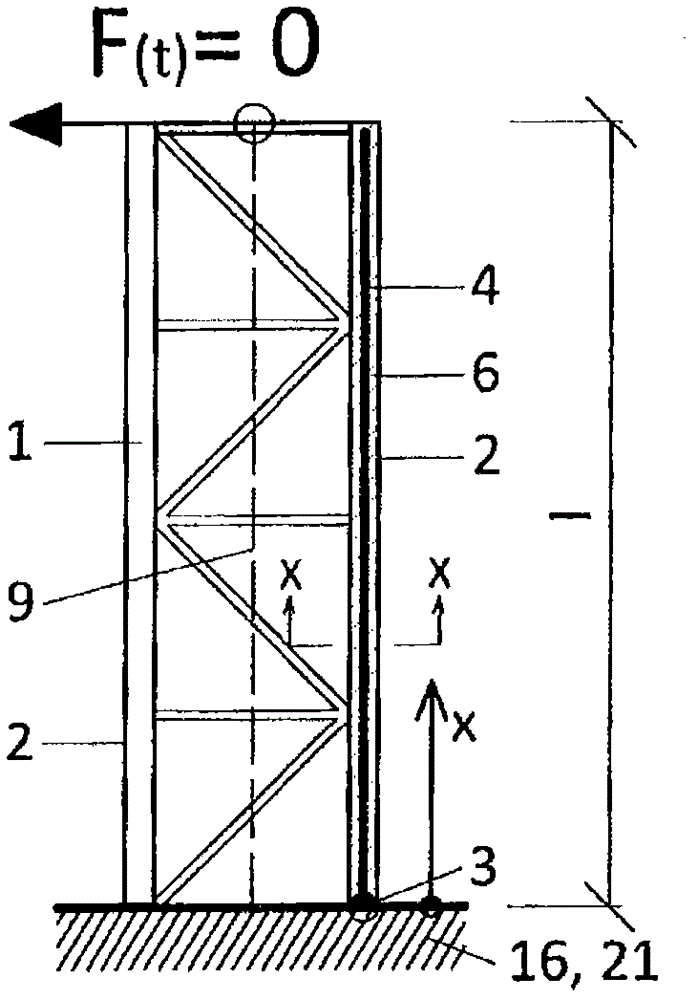
[0076] exist image 3 shown in the figure 1 Section of the load-carrying structure 1 with the rod 4 installed and the remaining volume of the cavity 5 filled with the material 6 . The rod 4 is fastened immovably at the abutment 21 by means of the anchor 3 . For a bett...


PUM


Abstract

In a load-bearing construction (1) having at least one load-bearing element (2), the load-bearing element (2) has at least one cavity (5) in which at least one rod (4) is disposed, the total cross-sectional area of all rods (4) each arranged in a cavity (5) being smaller than the cross-sectional area of this cavity (5), and the remaining volume of the cavity (5) being filled with a material (6). The rod (4) is displaceable along its length relative to the load-bearing element (2) when the load-bearing element (2) is deformed, the rod (4) being non-displaceably fixed at only one point relative to the load-bearing element (2) and being designed such that it dissipates energy upon the occurrence of a relative displacement with respect to the load-bearing element (2).

Description

technical field [0001] The invention relates to a carrier structure with at least one carrier element according to the preamble of claim 1 . Background technique [0002] The load-bearing structure can be, for example, a tall building, a chimney, a tower or a bridge. [0003] The load-bearing structure is formed, for example, from rods, beams, sheets or plates. A load-bearing structure in the field of construction technology has at least one support. Supports (lagers) or foundation structures (fundierungskonstruktion) can be used as supports. [0004] In load-bearing structures, vibrations can be excited by dynamic actions (earthquakes, wind, pedestrians on bridges, etc.). There are different methods to reduce vibrations. [0005] ●Change the frequency position (Frequenzlage) [0006] In order to reduce the vibrations, a natural frequency offset is provided as a countermeasure so that the distance from the excitation frequency (Erregerfrequenz) is as large as possible. ...

Claims


Application Information

Patent Timeline
Patent Type & Authority Patents(China)
IPC IPC(8): E01D11/00E01D19/16E04B1/98E04H9/02E04H9/14
CPCE01D6/02E04H9/028E04B1/985E04H9/02E04H9/0215E04H9/0237E01D22/00E04H9/021
Inventor J·科莱格P·埃格H·帕尔达切尔
Owner VSL INT AG
Learn More