Semiautomatic paying-off device

A pay-off device and semi-automatic technology, which is applied in the directions of transportation and packaging, transportation of filamentous materials, and processing of thin materials, etc., can solve the problems that the support frame is easily pulled down, the bending is not straight, the wire scrapes the burrs in the steel pipe, etc. Achieve the effect of stable and reliable connection, reduce rotation resistance, and reduce the difficulty of laying

Active Publication Date: 2012-03-28
五矿二十三冶建设集团有限公司
View PDF6 Cites 2 Cited by
  • Summary
  • Abstract
  • Description
  • Claims
  • Application Information

AI Technical Summary

Problems solved by technology

[0002] The ordinary pay-off device is composed of a pay-off shaft and a tripod support frame. Its disadvantages are as follows: 1. The pay-off shaft of the ordinary pay-off device is perpendicular to the support frame. If there are wires on the pay-off shaft, The force direction is also perpendicular to the supporting frame, which is easy to pull down the supporting frame; 2. When laying with an ordinary pay-off device, since the actual traction direction is not perpendicular to the direction of the rotation axis of the pay-off shaft, this requires a large force To pull the pay-off shaft to rotate, and the support frame is more likely to be pulled down, causing the wire to be damaged, or even unable to pull the pay-off shaft to rotate. In actual use, it is often necessary to increase personnel to operate beside the pay-off device; The line device uses a single pay-off shaft, and only one roll of wire can be laid at a time. If three rolls or more of wire are laid at the same time, a corresponding number of pay-off devices will be added. Phenomena such as straight and cross misalignment increase the difficulty of laying wires, and if the wires are not straight or the crosses are not straightened out, the wires may scrape the burrs in the steel pipe, causing the wires to break, and there is a danger of leakage and short circuit when the wires are electrified.

Method used


Image

  • Semiautomatic paying-off device
  • Semiautomatic paying-off device
  • Semiautomatic paying-off device

Examples


Embodiment Construction

[0019] The present invention will be further described in detail below in conjunction with the accompanying drawings and specific embodiments.

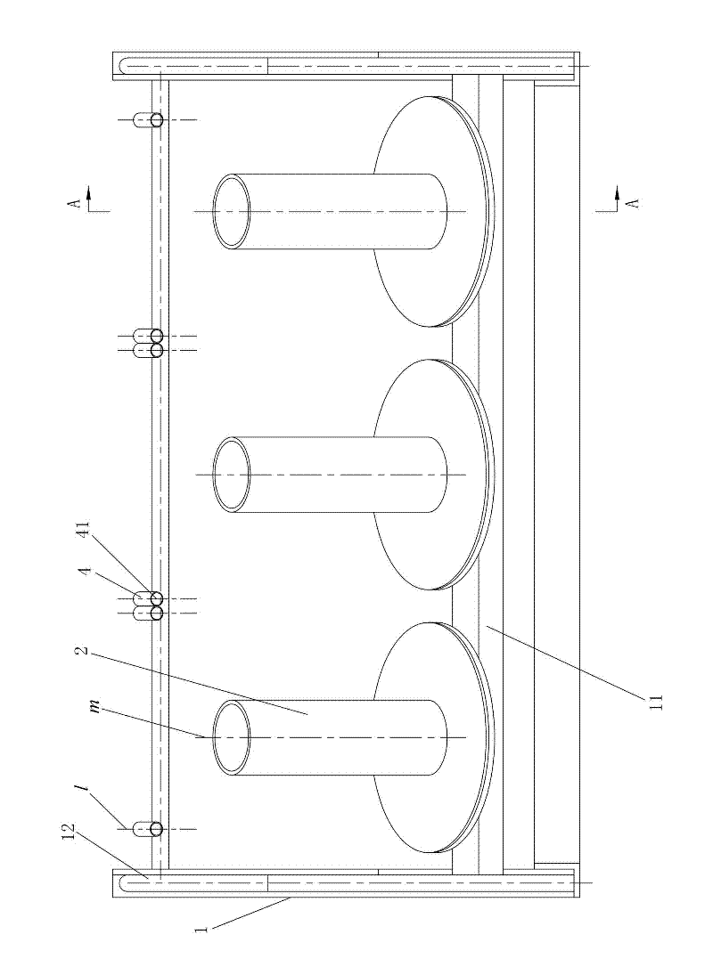
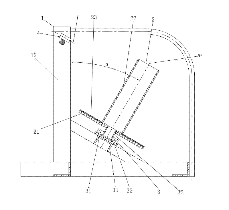
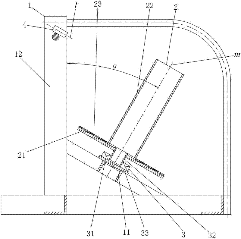
[0020] Such as figure 1 with figure 2 As shown, the semi-automatic pay-off device of the present invention includes a support frame 1 and three pay-off shaft frames 2, each pay-off shaft frame 2 is installed on the support frame 1 by a rotating assembly 3, and the three pay-off shaft frames Axis of rotation of frame 2 m They are arranged obliquely relative to the vertical direction. When the semi-automatic pay-off device is laid, it pulls the pay-off from the top of the pay-off shaft frame 2, which is not easy to be pulled down. It has good stability, and one semi-automatic pay-off device can simultaneously lay three Rolling wires is more efficient. In addition, two or more pay-off spools 2 can be set on the support frame 1 according to actual needs, so as to adapt to different working conditions.

[0021] In this embodiment, the ...


PUM


Abstract

The invention discloses a semiautomatic paying-off device. The semiautomatic paying-off device comprises a support bracket and a plurality of paying-off shaft brackets, wherein each paying-off shaft bracket is arranged on the support bracket through a rotating component; and the rotating axial lines of the paying-off shafts are arranged in an inclined way relative to the vertical direction. The semiautomatic paying-off device has the advantages that: the semiautomatic paying-off device has high paying-off stability, low laying difficulties and labor-saving operation, is not easy to pull down,can lay a plurality of wires at the same time, avoids bending, un-straight and cross-dislocation phenomena when wires are laid and the like.

Description

technical field [0001] The invention relates to the field of pay-off tools, in particular to a semi-automatic pay-off device for laying wires, cables and other laying objects. Background technique [0002] The ordinary pay-off device is composed of a pay-off shaft and a tripod support frame. Its disadvantages are as follows: 1. The pay-off shaft of the ordinary pay-off device is perpendicular to the support frame. If there are wires on the pay-off shaft, The force direction is also perpendicular to the supporting frame, which is easy to pull down the supporting frame; 2. When laying with an ordinary pay-off device, since the actual traction direction is not perpendicular to the direction of the rotation axis of the pay-off shaft, this requires a large force To pull the pay-off shaft to rotate, and the support frame is more likely to be pulled down, causing the wire to be damaged, or even unable to pull the pay-off shaft to rotate. In actual use, it is often necessary to incr...

Claims


Application Information

Patent Timeline
Patent Type & Authority Applications(China)
IPC IPC(8): B65H49/18B65H49/32B65H49/30
Inventor 余佳泉吴建国李卫周新武
Owner 五矿二十三冶建设集团有限公司
Why Eureka
Try Eureka